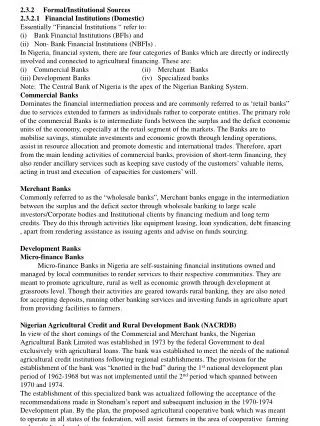
0 likes | 4 Views
CSCE-212-Introduction to Computer Architecture-Lecture3-Fall 2024-Mehdi Yaghouti
E N D
Review on Digital Design (Sequential Circuits) University of South Carolina Introduction to Computer Architecture Fall, 2024 Instructor: Mehdi Yaghouti MehdiYaghouti@gmail.com Introduction to Computer Architecture, 2024 1/32 University of South Carolina (M. Y.) USC
Storage Elements Maintains a binary state as long as power is on Provides control signals to switch the state Level sensitive storage elements: Latches Transition sensitive storage elements: Flip-Flops Latches are the building blocks of Flip-Flops Latches are useful for asynchronous designs Flip-Flops are the choice for synchronous circuits Introduction to Computer Architecture, 2024 2/32 University of South Carolina (M. Y.) USC
Latches Latches are level sensitive S and R stand for Set and Reset S = 1,R = 0 set the output S = 0,R = 1 reset the output S = 0,R = 0 retains the old value S = 1,R = 1 causes race condition (forbidden) Introduction to Computer Architecture, 2024 3/32 University of South Carolina (M. Y.) USC
D-Latches Latches are level sensitive S and R stand for Set and Reset S = 1,R = 0 set the output S = 0,R = 1 reset the output S = 0,R = 0 retains the old value S = 1,R = 1 causes race condition (forbidden) D-Latch eliminates the forbidden status Introduction to Computer Architecture, 2024 4/32 University of South Carolina (M. Y.) USC
D-Latches Latches are level sensitive S and R stand for Set and Reset S = 1,R = 0 set the output S = 0,R = 1 reset the output S = 0,R = 0 retains the old value S = 1,R = 1 causes race condition (forbidden) D-Latch eliminates the forbidden status Clk determines when change is allowed Introduction to Computer Architecture, 2024 5/32 University of South Carolina (M. Y.) USC
D Flip-Flop Master and Slave D-Latches connected back to back Master and Slave receives complementary clocks At Clk = 1, Master Latch is transparent At Clk = 0, Slave Latch is transparent Introduction to Computer Architecture, 2024 6/32 University of South Carolina (M. Y.) USC
Register Enable determines whether data is loaded Reset clear the output to 0 N-bit register is a bank of N Flip-Flops Introduction to Computer Architecture, 2024 7/32 University of South Carolina (M. Y.) USC
Register File 4×4-bits register file 2 Read ports 1 Write port log24 address bus 32×32-bits register file Introduction to Computer Architecture, 2024 8/32 University of South Carolina (M. Y.) USC
Synchronous Sequential Circuits The outputs and the next state are both a function of the inputs The state of the system is hold in flip flops Introduction to Computer Architecture, 2024 9/32 University of South Carolina (M. Y.) USC
There are two type of FSM Moore machines: The output depends directly only on the current state Mealy machines: The output depends on both current state and the input Finite State Machines Synchronous sequential circuits can be designed as Finite State Machines At each clock both the state and the output of the circuit will be updated The next state is computed based on both input and the current state Introduction to Computer Architecture, 2024 10/32 University of South Carolina (M. Y.) USC
Mealy machines: The output depends on both current state and the input Finite State Machines Synchronous sequential circuits can be designed as Finite State Machines At each clock both the state and the output of the circuit will be updated The next state is computed based on both input and the current state There are two type of FSM Moore machines: The output depends directly only on the current state Introduction to Computer Architecture, 2024 10/32 University of South Carolina (M. Y.) USC
Finite State Machines Synchronous sequential circuits can be designed as Finite State Machines At each clock both the state and the output of the circuit will be updated The next state is computed based on both input and the current state There are two type of FSM Moore machines: The output depends directly only on the current state Mealy machines: The output depends on both current state and the input Introduction to Computer Architecture, 2024 10/32 University of South Carolina (M. Y.) USC
State Diagram State Diagram: A visual representation that depicts state transitions and outcomes in response to inputs States: Different conditions a system can be in Transitions: Arrows showing movement between states Inputs: Triggers for state changes Reset state: Start and end points of the process State Actions: Actions within states or during transitions Introduction to Computer Architecture, 2024 11/32 University of South Carolina (M. Y.) USC
Moore Machine Design 1 Assigning binary codes to sates S0→ 00 S1→ 01 S2→ 10 S3→ 11 State coding is not unique and will affect the design Introduction to Computer Architecture, 2024 12/32 University of South Carolina (M. Y.) USC
Moore Machine Design 1 Assigning binary codes to sates 2 Obtain the binary-coded state table Introduction to Computer Architecture, 2024 13/32 University of South Carolina (M. Y.) USC
Moore Machine Design 1 Assigning binary codes to sates 2 Obtain the binary-coded state table 3 Obtain the equations for flip flops inputs Introduction to Computer Architecture, 2024 14/32 University of South Carolina (M. Y.) USC
Moore Machine Design 1 Assigning binary codes to sates 2 Obtain the binary-coded state table 3 Obtain the equations for flip flops inputs 4 Obtain the output equations in terms of states Introduction to Computer Architecture, 2024 15/32 University of South Carolina (M. Y.) USC
Moore Machine Design 1 Assigning binary codes to sates 2 Obtain the binary-coded state table 3 Obtain the equations for flip flops inputs 4 Obtain the output equations in terms of states 5 Draw the logic circuit diagram Introduction to Computer Architecture, 2024 16/32 University of South Carolina (M. Y.) USC
SystemVerilog Moore’s FSM implementation typedef,always ff, always comb Introduction to Computer Architecture, 2024 17/32 University of South Carolina (M. Y.) USC
Mealy Machine Design 1 Assigning binary codes to sates S0→ 00 S1→ 01 S2→ 10 State coding is not unique and will affect the design Introduction to Computer Architecture, 2024 18/32 University of South Carolina (M. Y.) USC
Mealy Machine Design 1 Assigning binary codes to sates 2 Obtain the binary-coded state table Introduction to Computer Architecture, 2024 19/32 University of South Carolina (M. Y.) USC
Mealy Machine Design 1 Assigning binary codes to sates 2 Obtain the binary-coded state table 3 Obtain the equations for flip flops inputs and outputs Introduction to Computer Architecture, 2024 20/32 University of South Carolina (M. Y.) USC
Mealy Machine Design 1 Assigning binary codes to sates 2 Obtain the binary-coded state table 3 Obtain the equations for flip flops inputs and outputs 4 Draw the logic circuit diagram Introduction to Computer Architecture, 2024 21/32 University of South Carolina (M. Y.) USC
SystemVerilog Mealy’s FSM implementation Introduction to Computer Architecture, 2024 22/32 University of South Carolina (M. Y.) USC
Timing Diagram Introduction to Computer Architecture, 2024 23/32 University of South Carolina (M. Y.) USC
tsetup: It’s the time input must have stabilized, before the rising edge thold: It’s the time input must have stabilized, after the rising edge tapr: It’s the sum tsetup+ thold tccq: It’s the contamination delay from the clock to output of the flip flops tpcq: It’s the propagation delay from the clock to output of the flip flops The clock cycle Tcmust be long enough for all the signals to be settled The clock frequency is given by Fc= 1 Tc Timing Specification Introduction to Computer Architecture, 2024 24/32 University of South Carolina (M. Y.) USC
thold: It’s the time input must have stabilized, after the rising edge tapr: It’s the sum tsetup+ thold tccq: It’s the contamination delay from the clock to output of the flip flops tpcq: It’s the propagation delay from the clock to output of the flip flops The clock cycle Tcmust be long enough for all the signals to be settled The clock frequency is given by Fc= 1 Tc Timing Specification tsetup: It’s the time input must have stabilized, before the rising edge Introduction to Computer Architecture, 2024 24/32 University of South Carolina (M. Y.) USC
tapr: It’s the sum tsetup+ thold tccq: It’s the contamination delay from the clock to output of the flip flops tpcq: It’s the propagation delay from the clock to output of the flip flops The clock cycle Tcmust be long enough for all the signals to be settled The clock frequency is given by Fc= 1 Tc Timing Specification tsetup: It’s the time input must have stabilized, before the rising edge thold: It’s the time input must have stabilized, after the rising edge Introduction to Computer Architecture, 2024 24/32 University of South Carolina (M. Y.) USC
tccq: It’s the contamination delay from the clock to output of the flip flops tpcq: It’s the propagation delay from the clock to output of the flip flops The clock cycle Tcmust be long enough for all the signals to be settled The clock frequency is given by Fc= 1 Tc Timing Specification tsetup: It’s the time input must have stabilized, before the rising edge thold: It’s the time input must have stabilized, after the rising edge tapr: It’s the sum tsetup+ thold Introduction to Computer Architecture, 2024 24/32 University of South Carolina (M. Y.) USC
tpcq: It’s the propagation delay from the clock to output of the flip flops The clock cycle Tcmust be long enough for all the signals to be settled The clock frequency is given by Fc= 1 Tc Timing Specification tsetup: It’s the time input must have stabilized, before the rising edge thold: It’s the time input must have stabilized, after the rising edge tapr: It’s the sum tsetup+ thold tccq: It’s the contamination delay from the clock to output of the flip flops Introduction to Computer Architecture, 2024 24/32 University of South Carolina (M. Y.) USC
The clock cycle Tcmust be long enough for all the signals to be settled The clock frequency is given by Fc= 1 Tc Timing Specification tsetup: It’s the time input must have stabilized, before the rising edge thold: It’s the time input must have stabilized, after the rising edge tapr: It’s the sum tsetup+ thold tccq: It’s the contamination delay from the clock to output of the flip flops tpcq: It’s the propagation delay from the clock to output of the flip flops Introduction to Computer Architecture, 2024 24/32 University of South Carolina (M. Y.) USC
1 The clock frequency is given by Fc= Tc Timing Specification tsetup: It’s the time input must have stabilized, before the rising edge thold: It’s the time input must have stabilized, after the rising edge tapr: It’s the sum tsetup+ thold tccq: It’s the contamination delay from the clock to output of the flip flops tpcq: It’s the propagation delay from the clock to output of the flip flops The clock cycle Tcmust be long enough for all the signals to be settled Introduction to Computer Architecture, 2024 24/32 University of South Carolina (M. Y.) USC
Timing Specification tsetup: It’s the time input must have stabilized, before the rising edge thold: It’s the time input must have stabilized, after the rising edge tapr: It’s the sum tsetup+ thold tccq: It’s the contamination delay from the clock to output of the flip flops tpcq: It’s the propagation delay from the clock to output of the flip flops The clock cycle Tcmust be long enough for all the signals to be settled The clock frequency is given by Fc= 1 Tc Introduction to Computer Architecture, 2024 24/32 University of South Carolina (M. Y.) USC
Timing Specification Determine the minimum clock cycle in the following circuit Introduction to Computer Architecture, 2024 25/32 University of South Carolina (M. Y.) USC
We must have: Tc≥ tpcq+ tpd+ tsetup Timing Specification Determine the minimum clock cycle in the following circuit Based on the following timing constraints, Introduction to Computer Architecture, 2024 26/32 University of South Carolina (M. Y.) USC
Timing Specification Determine the minimum clock cycle in the following circuit Based on the following timing constraints, We must have: Tc≥ tpcq+ tpd+ tsetup Introduction to Computer Architecture, 2024 26/32 University of South Carolina (M. Y.) USC
Timing Specification Determine the minimum clock cycle in the following circuit Based on the following timing constraints, We must have: Tc≥ tpcq+ tpd+ tsetup thold≤ tccq+ tcd Introduction to Computer Architecture, 2024 27/32 University of South Carolina (M. Y.) USC
Timing Specification (Example) Determine the max and min delay for the given circuit Introduction to Computer Architecture, 2024 28/32 University of South Carolina (M. Y.) USC
Timing Specification (Example) Determine the max and min delay equation for the given circuit Introduction to Computer Architecture, 2024 29/32 University of South Carolina (M. Y.) USC
Timing Specification (Example) Determine the max and min delay equation for the given circuit Tc≥ tpcq+ 3tpd+ tsetup Introduction to Computer Architecture, 2024 30/32 University of South Carolina (M. Y.) USC
Timing Specification (Example) Determine the max and min delay equation for the given circuit Tc≥ tpcq+ 3tpd+ tsetup thold≤ tccq+ tcd Introduction to Computer Architecture, 2024 31/32 University of South Carolina (M. Y.) USC
Question Determine the maximum Fc and maximum tolerable thold for the following circuit Fmax=? thold=? Introduction to Computer Architecture, 2024 32/32 University of South Carolina (M. Y.) USC