Electronic Components Electronics Unit, Lecture 2
Electronic Components Electronics Unit, Lecture 2 Identification of components and handling precautions to protect them from damage due to electrostatic discharge Passive Components Resistors Capacitors Inductors Diodes Interface components Resistors

Electronic Components Electronics Unit, Lecture 2
E N D
Presentation Transcript
Electronic ComponentsElectronics Unit, Lecture 2 Identification of components and handling precautions to protect them from damage due to electrostatic discharge Electronics 2
Passive Components Resistors Capacitors Inductors Diodes Interface components Electronics 2
Resistors Values specified in ohms (Ω), kilo-ohms (K), or mega-ohms (M) Marked with value using a color code 0 1234567895%10% Big Bears Run Over Your Gladiola Bed Vexing Garden Worms (go see now) Electronics 2
Resistor ratings Physical size of resistors determines power handling ability Commonly available as 1/8, 1/4, 1/2, 1, and 2 watt components Much higher powers available , usually as wirewound or ceramic encapsulated parts Electronics 2
Resistor handling and installation Resistors are not polarized and may be installed in either direction. Resistors are not generally susceptible to ESD damage, so special precautions are not required. Mechanical stress due to lead bending should be minimized. Electronics 2
Capacitors Values specified in microfarads (μF) or picofarads (pF) Marked with actual value or a numeric code Some varieties are +/- polarized Electronics 2
Capacitor types Ceramic disk Monolithic ceramic Dipped silvered-mica Mylar or polyester Aluminum electrolytic (+/-) Tantalum (+/-) Ceramic disk Monolithic ceramic Dipped siver-mica Mylar Mylar Solid tantalum, polarized Radial aluminum electrolytic Axial aluminum electrolytic Electronics 2
Capacitor ratings Physical size of capacitors is related to voltage handling ability – WVDC – working voltage DC Temperature coefficient may also be important – can be + or – or nearly zero Temperature coefficient depends upon dielectric material Electronics 2
Capacitor handling and installation Most capacitors are not polarized and may be installed in either direction. Electrolytic capacitors ARE polarized and MUST be installed with proper polarity, else catastrophic failure! Capacitors are not generally susceptible to ESD damage, so special precautions are not required. Mechanical stress due to lead bending should be minimized. Electronics 2
Inductors Values specified in henries (H), millihenries (mH) and microhenries (μH) A coil of wire that may be wound on a core of air or other non-magnetic material, or on a magnetic core such as iron powder or ferrite. Two coils magnetically coupled form a transformer. Electronics 2
Inductor types Molded inductor & air-wound inductor Adjustable air-wound inductor Ferrite core toroidal transformer Air wound inductor Iron powder toroidal inductor Electronics 2
Inductor ratings Wire gauge and physical size of the coil determine the current handling capacity. Core material will have a temperature dependence. Air is best, followed by iron powder, then ferrites. Electronics 2
Inductor handling and installation Inductors are not polarized and may be installed in either direction. Inductors are not generally susceptible to ESD damage, so special precautions are not required. Mechanical stress due to lead bending should be minimized. Inductors in timing or frequency determining circuits should be installed in a mechanically rigid fashion. Electronics 2
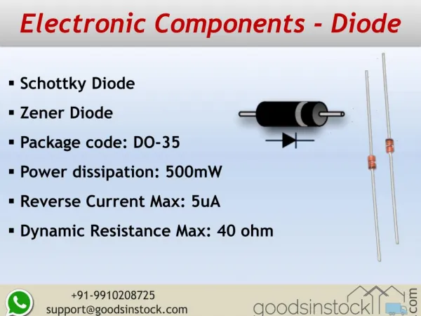
Diodes Most modern diodes are semiconductor devices, but are considered passive since they do not contribute any amplification or gain to a circuit. Cathode Anode Electronics 2
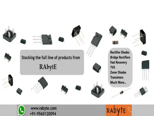
Diode types May be classified by semiconductor material silicon, germanium, gallium arsenide, etc. Or classified by circuit function Small signal detector or switching diode Rectifier diode Light-emitting diode (LED) Electronics 2
Diode Ratings Peak inverse voltage (PIV) Maximum forward current (IF) Maximum forward voltage drop (VF) Reverse leakage current (IR) Electronics 2
Diode handling and installation Diodes are polarized and must be installed in with correct orientation. Many diodes are modestly susceptible to ESD damage, so normal ESD precautions should be taken. Mechanical stress due to lead bending should be minimized. Electronics 2
Interface components Switches Plugs Sockets Panel controls Electronics 2
Two common plug styles Sleeve Ring Tip 1/8” stereo phone plug 1/8” mono phone plug Shield Tip RCA plug Sleeve Tip Electronics 2
Active Components Transistors Bipolar Field effect Integrated circuits Analog Digital Microcontroller Electronics 2
Transistors Three terminal devices manufactured in a variety of package styles. Can you find the three terminals of this, the very first transistor? Electronics 2
Terminal Designations and packaging styles Collector Base Emitter 2N2222A in a TO-18 package 2N2222 in a TO-92 package Drain Gate 2SC2078 in a TO-220 package Source Electronics 2
Transistor handling and installation Transistors are polarized and must be installed in with correct orientation. Most BJT transistors are modestly susceptible to ESD damage, so normal ESD precautions should be taken. MOSFET (IGFET) transistors are very susceptible to ESD damage, so rigorous precautions should be taken. Mechanical stress due to lead bending should be minimized. Electronics 2
Integrated Circuits Integrated circuits (ICs) are multi-terminal devices that provide an array of functions and applications far to numerous to list here. Electronics 2
Pin identification and numbering convention Pin 8 Pin 14 Pins are numbered sequentially in a counterclockwise direction. Pin 1 is often identified with a dot or a dimple. The pin 1 end of the chip is often identified with a notch. Notch Dimple Pin 7 Pin 1 Electronics 2
IC handling and installation ICs are polarized and must be installed with correct orientation. Observe pin 1 location on sockets or circuits. Treat all ICs as if they are very susceptible to ESD damage (very many actually are), so rigorous precautions should be taken. Leads generally should not be bent. Electronics 2
Electrostatic Discharge (ESD) Protection Ground your work surface Use an anti-static mat Ground your tools (i.e., soldering iron) Many irons are constructed with a grounded tip Ground yourself Use a wrist or ankle strap, but always include a series resistor of high value to avoid any shock hazard. Touch a grounded object before handling static sensitive components. Electronics 2
Activity E-2 http://www.kpsec.freeuk.com/symbol.htm Inventory the parts supplied in your SkeeterSatkit. A complete parts list is provided. Determine if any parts require ESD precautions. Sort the parts into groups according the component types you have studied today Determine the value and tolerance of each part as appropriate. Electronics 2