Download
1 / 65
680 likes | 1.79k Views
Natural Gas Engine Drive Air Compressor Training. Industrial Center, Inc. Chicago, Illinois April 9, 1997. Allen L. Humphrey Industrial Marketing Manager Ingersoll-Rand Company Portable Compressor Division Air Compressor Group Mocksville, North Carolina. Air Compressor Basics Presented By:.

E N D
Natural Gas Engine DriveAir Compressor Training Industrial Center, Inc. Chicago, Illinois April 9, 1997
Allen L. HumphreyIndustrial Marketing ManagerIngersoll-Rand CompanyPortable Compressor DivisionAir Compressor GroupMocksville, North Carolina Air Compressor Basics Presented By:
Isn’t all gas natural!!! Hi !, I’m an expert in Natural Gas ! Gas Company Guy Air Compressor Guy
I'm in trouble now, another guy full of hot air!!! I’m an expert in compressed air,! Hot air, cooled, and dried Air Compressor Guy Gas Company Guy
Outline: I. Compressed Air Facts II. Compressed Air Technologies III. Regulation & Controls IV. System Location and Arrangement V. Compressor System Components - The Basics
Compressed Air Facts • Most facilities consider compressed air a utility on par with electricity, gas, and water • However, few operating people know the real operating cost of their compressed air system
What is cost per CFM ? A Good Approximation • Typical Compressor produces 4 CFM per 1 Hp • 1 Hp = 0.746/0.9 = 0.829kW • Therefore, 1 CFM = 0.207kW • @ 0.06 $/kw-hr, 1 cfm = $0.0124/hr • 10 CFM over 8000 hours costs 10 x 8000 x 0.124 = $ 992.00
Where are NORMAL savings ? • Fix System Leaks !! • Standard plant air system • 8000 hrs per year operation • Electrical costs = $ 0.06/kWhr • Plant line pressure = 100 PSIG • (1) 1/8th inch air leak = 26 CFM • 26 x 8000 x $.0124/hr = $ 2,579.00 • A typical plant can have air leaks = to 20% of total air usage.
Air Basics • Three Main Parameters • 1. Pressure • 2.Capacity • 3. Horsepower
Pressure(PSI) = Pounds per Square inch • Completely dependent on system, controls and safety valves • An unregulated compressor will make ever increasing pressure until a failure occurs • When plant capacity demand exceeds system capacity(CFM), compressor discharge pressure will drop
Pressure - Capacity Relationship P1= Initial pressure V1= Initial capacity P1 x V1 = P2 x V2 P2= Final pressure V2= Final capacity If a system needs more capacity(CFM) than available, plant pressure drops in an unsuccessfultrade of pressure for capacity
The Cost of Pressure Good Rule of Thumb Each # (PSI) of system pressure = 0.5% of system horsepower
Pressure Cost Example • 100Hp compressor set to discharge at 125 psig to plant system • Plant system only requires 110 psig • User resets compressor discharge pressure to 110 psig ( a 15 psi reduction) • 15 PSI = 7.5 % of Hp = 7.5 Hp • 7.5 x .746/.85 = 6.6kW x 8000 hrs x $.06/kWhr = $ 3,168.00 (Savings)
Capacity(Flow) = CFM(ft3per minute) • Basic measure of true compressor output • A fixed value in most designs, for a given model • Most all capacity measurements are referred back to inlet conditions. Capacity varies only slightly with a change in discharge pressure, for a given model
Capacity Measurement • In the pneumatics industry, ALL capacities are measured referring back to inlet conditions • Various formulae are used to define capacity(CFM): SCFM; ACFM; ICFM; FAD, etc. Require your vendor to define which and where • ASME and CAGI-Pneurop have generally accepted testing standards • Capacity tolerances may vary from vendor to vendor. Request definition
Horsepower • Typically, electric motor nameplate HP or NG engine MCHP(Max Continous Hp) • The work it takes to compress “X” CFM up to “Y” PSI • Driver HP is usually fixed. If either CFM or PSI is increased, the driver may overload, unless regulation, a speed reduction, or a change in either CFM or PSI takes place. • Horsepower tolerances may vary from vendor to vendor. Request definition
Air Basics Translations • Capacity(CFM) does the work; Pressure effects the rate at which the work is done • A trending decrease in plant air pressure typically indicates a requirement for more capacity(CFM), not pressure • Increasing or decreasing the existing compressor discharge pressure will normally have negligble effect on the compressor capacity
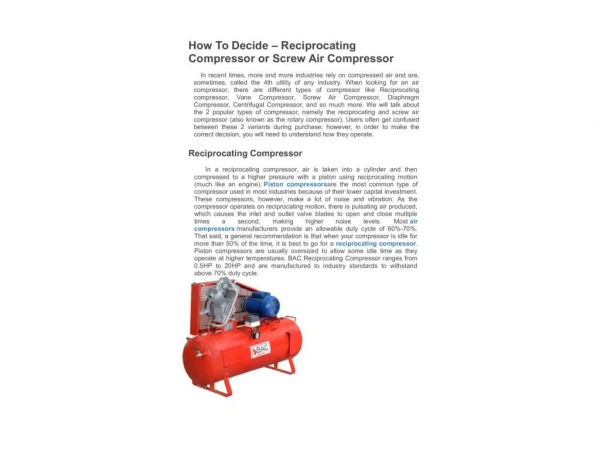
Compressor Technology Air Compressors Dynamic Displacement Positive Displacement Rotary Screw Centrifugal Reciprocating Single Acting Double Acting Oil Free Oil Flooded Single Stage Two Stage Lower Technology Higher Technology
Dynamic Displacement “Performance Curve”
Centrifugal Compressors • Advantages • Only real option over 600+ Hp • High air quality- 0 PPM oil carryover • Moderate to high efficiency • Longer design life than Rotaries • Disadvantages • Higher initial cost • Fluid cooled only • Power reduction down to 70% flow • Constant speed operation
Positive Displacement “Performance Curve”
Positive Displacement • Reciprocating or Rotary Screw Designs • Constant cfm; Variable pressure • Adaptable to variable speed drive • Variable speed and unloading provide close alignment with system demand • Oil Flooded Rotary Screws--The design of choice for NGEDAC’s
Rotary Screw Oil Flooded- Single Stage • Advantages • Low 1st cost; Low maintenance $ • Simple packaged design • Adaptable to variable speed drive • Disadvantages • Somewhat lower efficiency • Moderate durability - 10 15 years on average
Rotary Screw • Oil Free • Advantages • High air quality- 0 PPM oil carryover • Moderate efficiency • Packaged design • Disadvantages • Higher initial cost • Higher maintenance cost
Compressor Selection Criteria • Evaluated First Cost • Efficiency • Controls • Maintenance • Cooling • Air Quality • Durability
General Guidelines- First Cost • Single-stage rotary screw • Typically lowest first cost • Greatest market growth, largest population • Typically lowest efficiency • Possible Alternatives • Two-stage rotary screw • Oil free rotary screw* • Centrifugal* *Dependent on air quality requirements
General Guidelines- Maintenance • Capabilities of on site maintenance personnel ? Contract maintenance ? • Oil flooded rotaries typically require lowest maintenance • “Air-in-the-box” design enables on site overhauls of both compressor system and engine
General Guidelines- Cooling • Fluid-Air cooled - less expensive • Most designs have fluid or fluid-air cooled design options available • Closed evaporative cooling towers; open towers and external fluid to air coolers are viable cooling options
Regulation/Controls Applications • Average number of compressors = 2.5 per facility • Typical system controls: manual/ none • Each incremental 1 PSIG of unnecessary pressure cost 0.5% of compressor horsepower • Each electric motor driven compressor running unloaded = 35-50% of the full loaded electrical costs
Regulation Basics • Do not run compressors unnecessarily • Evaluate current regulation parameters • Consider upgrading substandard controls • The most efficient operating point is 100% full load.
Basic Types of Regulation This information will be covered in detail later in the seminar presentation
Possible Locations #1 FACILITY
Outdoors • Advantages • Zero floor space • Zero heat load • Disadvantages • Potential weather damage (Freezing, water, etc.) • Potential lack of maintenance (Out of sight, out of mind)
Possible Locations #1 FACILITY #2
Indoors Centralized • Advantages • Protected from elements • Potentially easier access • Disadvantages • Greatest floor space • Potentially long piping runs
Possible Locations #1 FACILITY #3 #3 #3 #2
Indoors Decentralized • Advantages • Possible to install closest to large air users • Least amount of pressure drop through air lines • Disadvantages • Highest probability of incorrect regulation • Potential to spread noise and heat complaints to broadest number of employees
Environmental Factors • Temperature • Ventilation • Conditions • Atmosphere • Personnel
Temperature - Low • Below 350F • Possible control freeze problem • Possible condensate freeze problem • Possible fluid misapplication • Recommendations • Heaters • Heat tracing key elements • Relocate
Temperature - High • Above 1000F • Possible unit shutdown • Increased engine maintenance • Possible decreased lubricant life • Recommendations • Improved ventilation/relocate • Higher performance lubricant • More suitable equipment design
Ventilation • Insufficient Ventilation • Possible unit shutdown • Increased maintenance • Possible decreased lubricant life • Requirements • Air-cooled • Water-cooled
Ventilation - The High Air Temperature (HAT) Vicious Cycle CompressorGenerates Heat Insufficient Ventilation Causes Heat To Remain Around Unit Unit TemperatureSpirals Upward This Heat is Ingested By Engine-Compressor Increasing Operating Temperatures Of Unit
Miscellaneous Conditions • Atmosphere • Personnel These important subjects will be covered later in the Seminar
Real World Systems Design Criteria • Air Quality required by User • Moisture content ? • Oil carryover ? • Contaminants • Pressure Drop • Demand Characteristics • Energy profile