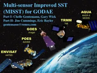
MODIS OVERVIEW at NASA HQ REVIEW August 23, 2005 of EOS AQUA INSTRUMENT ANOMALIES Vincent V. Salomonson MODIS Science Te
MODIS OVERVIEW at NASA HQ REVIEW August 23, 2005 of EOS AQUA INSTRUMENT ANOMALIES Vincent V. Salomonson MODIS Science Team Leader X. (Jack) Xiong MODIS Characterization Support Team (MCST) Leader And MODIS Project Scientist. MODIS Key Specifications. Instrument Overview .

MODIS OVERVIEW at NASA HQ REVIEW August 23, 2005 of EOS AQUA INSTRUMENT ANOMALIES Vincent V. Salomonson MODIS Science Te
E N D
Presentation Transcript
MODIS OVERVIEW at NASA HQ REVIEW August 23, 2005 of EOS AQUA INSTRUMENT ANOMALIES Vincent V. Salomonson MODIS Science Team Leader X. (Jack) Xiong MODIS Characterization Support Team (MCST) Leader And MODIS Project Scientist
Instrument Overview MODIS RSB Key Specifications
Instrument Overview MODIS TEB Key Specifications
Ocean Chlorophyll (top) and sea surface temperature (SST) observed via the Aqua MODIS instrument.
MODIS/Aqua & SeaWiFS Global Mean Chlorophyll Time Series: Consistency Clear-water: chl-a < 0.15 mg/m3 Deep-water: depth > 1000 m • Coastal: depth < 1000 m • Offset due to chlorophyll-a algorithm difference at high concentrations Dashed line: MODIS Solid line: SeaWiFS
Frequency of clear sky conditions (cloud fraction less than 20% in 1° grid box) over land (King, Platnick, et al. NASA/GSFC
2-D probability density function of cloud visible optical thickness and effective radius for marine boundary layer clouds off the coast of California. (King/Platnick, et al., NASA/GSFC
MODIS/Terra+Aqua Albedo 16-Day L3 Global 0.05Deg CMG for July 2002 (C. Schaaf, A Strahler---Boston College
Fires continued in central Alaska, as seen in this MODIS Aqua image. According to the Fairbanks North Star Borough, air quality conditions are hazardous (Code Maroon, over 300 ug/m3). Hourly concentrations earlier in the week spiked over 1000 ug/m3. According to AIRNow, hazardous conditions are expected to continue.
Global emissivity of land surfaces from MODIS (Zhengming Wan--UCSB The 5km MODIS LST product retrieved by the day/night LST algorithm from MODIS data provides new knowledge of emissivities at 3.75µm, 3.96µm, 4.05µm, 8.75µm, 11µm and 12µm (MODIS bands 20, 22, 23, 29, and 31-32) at the global scale
EOS Direct Readout Sites • ~100 Ingest sites around the world for Terra/Aqua DB downlink • Over 800 Users of data extending from 82 ingest sites • List is located on the Direct Readout Portal
MODIS On-orbit Calibration and Characterization MODIS On-board Calibrators (OBCs) Page 13
Schematic of MODIS On-orbit Calibration SDSM Solar Diffuser SRCA SDSM Blackbody SD/SDSM (weekly first year to bi-weekly) SRCA (monthly radiometric, bi-monthly spatial, quarterly spectral) BB (quarterly warm-up) Maneuvers (roll: monthly Moon; yaw: 2 for Terra and 1 for Aqua; pitch: 2 for Terra) Scan Mirror Space View Moon Starting from July 2, 2003, Terra MODIS SD door fixed at open with SD screen down; more efforts for SD calibration data analysis Page 14
Aqua Spatial Characterization (along-track) Days are counted from 2002
Aqua Spatial Characterization (along-scan) Days are counted from 2002
Spatial and Spectral Characterization Using SRCA Spatial Frame -> x Spectral Grating step -> q Page 20
SRCA Functions In the spectral calibration mode, a light source from the integrating sphere (SIS) provides illumination for the visible (VIS), near infrared (NIR), and short wave infrared (SWIR) bands. The light coming from the integrating sphere is bounced off of a toroidal (3-D doughnut shape) relay mirror into the entrance of a modified Czerny-Turner monochromator (an instrument that obtains the light of one wavelength or very narrow band of the light spectrum). The monochromator contains a motor-driven grating/mirror assembly, which is used in conjunction with a filter wheel (to block out-of-band energy) to diffract the light into one of the VIS, NIR, or SWIR bands. The diffracted light coming out of the monochromator is then sent into a Cassegrain telescope that moves the light to the right elevation and angle (called collimating) and then bounces it off of a fixed-fold mirror onto the Scan Mirror. The light from this point moves through MODIS’ main optical system and onto the detectors where the resultant calibration data is integrated into the general scan data. At minimum, one SRCA spectral wavelength measurement is taken per revolution of the Scan Mirror. Computer modeling has shown that the accuracy of this calibration method is within 1 nanometer. The SRCA system is also able to perform self-calibration by inserting didymium glass near the light source and sensing the SRCA’s response profile using a photodiode at the exit of the monochromator. In the radiometric calibration mode, the entrance and exit slits to the SRCA are open and a silvered mirror replaces the grating. This difference makes the monochromator into a relay, where light from the integrating sphere is sent to the entrance aperture for the calibration of MODIS’ reflective bands. In this mode, the SRCA is designed to provide six radiance levels that are stable to within one percent over an orbital period of 100 minutes. This stability is achieved by a radiance feedback loop that is based on input from a temperature-controlled photodiode.
SRCA Functions (continued) In the spatial registration mode, the entrance to the monochromator is open, and a reticle pattern (a grid or pattern that establishes scale or position) is placed at the exit of the monochromator. In addition to the VIS-NIR-SWIR illumination, the radiation from a resistive heater is coupled into the system via an ITO dichroic beamsplitter (splits the light into two colors), which provides energy to support the spatial registration for the thermal bands. The specially designed reticle patterns at the exit slit of the monochromator are then projected into the MODIS optical system, which are then re-imaged and scanned by the various FPAs to generate the data for the spatial registration algorithm. The result is a record of the FPA spatial registration over the life of the instrument, which is very important to demonstrating MODIS’ reliability.
Terra Spatial Characterization (along-scan) SD door open impact.