Download
1 / 66
710 likes | 1.81k Views
Collegiate Design Series Suspension 101. Steve Lyman Formula SAE Lead Design Judge DaimlerChrysler Corporation. There Are Many Solutions. “It depends.” “Everything is a compromise.”. Suspension 101. Ride Frequency/ Balance (Flat Ride) Motion Ratios Ride Friction

E N D
Collegiate Design SeriesSuspension 101 Steve Lyman Formula SAE Lead Design Judge DaimlerChrysler Corporation
There Are Many Solutions • “It depends.” • “Everything is a compromise.”
Suspension 101 • Ride Frequency/ Balance (Flat Ride) • Motion Ratios • Ride Friction • Suspension Geometry Selection • Suspension Layouts- Double A Arm Variations and Compromises • Dampers- A Really Quick Look
“The thing we had missed was that the excitation at front and rear did not occur simultaneously. The actual case was more like this-- Time Lag --with the angle of crossing of the two wave lines representing the severity of the pitch.” (From Chassis Design: Principles and Analysis, Milliken & Milliken, SAE 2002)
“By arranging the suspension with the lower frequency in front (by 20% to start) this motion could be changed to-- --a much closer approach to a ‘flat’ ride”. (From Chassis Design: Principles and Analysis, Milliken & Milliken, SAE 2002)
Does motion ratio affect forces transmitted into the body? • Motion ratio is spring travel divided by wheel travel. • The force transmitted to the body is reduced if the motion ratio is increased.
T L Does motion ratio affect forces transmitted to the body? Wheel Rate: 150 lb/in Motion Ratio: 0.5 Not good Force at wheel for 1” wheel travel = 150 lb Spring deflection for 1” wheel travel=0.5” Force at spring for 1” wheel travel = 300 lb Force at body = Force at wheel / MR Spring Rate=300 lb / 0.5 = 600 lb/in Spring Rate= Wheel Rate / MR2
Small inputs don’t “break through” the friction, resulting in artificially high ride frequency (From Chassis Design: Principles and Analysis, Milliken & Milliken, SAE 2002) How does ride friction affect frequency? (3.16 Hz) (1.05 Hz)
Ride Summary • Flat Ride • Improves handling, acceleration, braking performance • Plenty of suspension travel • Allows lower spring rates & ride frequencies • Allows progressive jounce bumper engagement • Good motion ratio • Reduces loads into vehicle structure • Increases shock velocity, facilitates shock tuning • 1.00:1 is ideal, 0.60:1 minimum design target • Stiff structure (The 5th Spring) • Improves efficiency of chassis and tire tuning • Provides more consistent performance on the track • Applies to individual attachment compliances, 5:1 minimum design target, 10:1 is ideal • Successful SAE designs in the 2000-3000 ft-lbs/deg range (static torsion), 2X for static bending (lbs/in) • Low Friction • Permits dampers to provide consistent performance • Not masked by coulomb friction (stiction) • 40:1 minimum (corner weight to frictional contribution for good SLA suspension
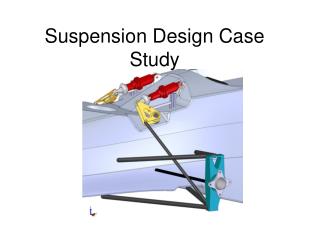
Suspension Geometry Setup • Front Suspension 3 views • Rear Suspension 3 views
Front Suspension Front View • Start with tire/wheel/hub/brake rotor/brake caliper package. • pick ball joint location. • pick front view instant center length and height. • pick control arm length. • pick steering tie rod length and orientation. • pick spring/damper location.
FSFV: wheel/hub/brake package • Ball joint location establishes: • King Pin Inclination (KPI): the angle between line through ball joints and line along wheel bearing rotation axis minus 90 degrees. • Scrub radius: the distance in the ground plan from the steering axis and the wheel centerline. • Spindle length: the distance from the steer axis to the wheel center.
From The Automotive Chassis: Engineering Principles, J. Reimpell & H. Stoll, SAE 1996 Spindle Length Spindle Length King Pin Inclination Angle Scrub Radius (positive shown) Scrub Radius (negative shown)
FSFV: wheel/hub/brake package • KPI effects returnability and camber in turn. • KPI is a result of the choice of ball joint location and the choice of scrub radius.
FSFV: wheel/hub/brake package • Scrub radius determines: • the sign and magnitude of of the forces in the steering that result from braking. • a small negative scrub radius is desired. • Scrub radius influences brake force steer.
FSFV: wheel/hub/brake package • Spindle length determines the magnitude of the forces in the steering that result from: • hitting a bump • drive forces on front wheel drive vehicles • Spindle length is a result of the choice of ball joint location and the choice of scrub radius.
FSFV: wheel/hub/brake package • Front view instant center is the instantaneous center of rotation of the spindle (knuckle) relative to the body. • Front view instant center length and height establishes: • Instantaneous camber change • Roll center height (the instantaneous center of rotation of the body relative to ground)
From Car Suspension and Handling 3rd Ed, D. Bastow & G. Howard, SAE 1993
FSFV: wheel/hub/brake package • The upper control arm length compared to the lower control arm length establishes: • Roll center movement relative to the body (vertical and lateral) in both ride and roll. • Camber change at higher wheel deflections.
(From Suspension Geometry and Design, John Heimbecher, DaimlerChrysler Corporation)
FSFV: Roll Center Movement • Ride and roll motions are coupled when a vehicle has a suspension where the roll center moves laterally when the vehicle rolls. • The roll center does not move laterally if in ride, the roll center height moves 1 to 1 with ride (with no tire deflection).
FSFV: wheel/hub/brake package • The steering tie rod length and orientation (angle) determines the shape (straight, concave in, concave out) and slope of the ride steer curve.
FSFV: wheel/hub/brake package • The spring location on a SLA suspension determines: • the magnitude of the force transmitted to the body when a bump is hit (the force to the body is higher than the force to the wheel) • the relationship between spring rate and wheel rate (spring rate will be higher than wheel rate) • how much spring force induces c/a pivot loads • An offset spring on a strut can reduce ride friction by counteracting strut bending (Hyperco gimbal-style spring seat).
From The Automotive Chassis: Engineering Principles, J. Reimpell & H. Stoll, SAE 1996 Spring axis aligned with kingpin axis (not strut CL)
Front Suspension Side View • Picking ball joint location and wheel center location relative to steering axis establishes: • Caster • Caster trail (Mechanical Trail)
From The Automotive Chassis: Engineering Principles, J. Reimpell & H. Stoll, SAE 1996
Front Suspension Side View • Picking the side view instant center location establishes: • Anti-dive (braking) • Anti-lift (front drive vehicle acceleration)
Front Suspension Side View • Anti-dive (braking): • Instant center above ground and aft of tire/ground or below ground and forward of tire/ground. • Increases effective spring rate when braking. • Brake hop if distance from wheel center to instant center is too short.
Front Suspension Plan View • Picking steer arm length and tie rod attitude establishes: • Ackermann • recession steer • magnitude of forces transmitted to steering
Front Suspension: Other Steering Considerations • KPI and caster determine: • Returnability • The steering would not return on a vehicle with zero KPI and zero spindle length • camber in turn
From The Automotive Chassis: Engineering Principles, J. Reimpell & H. Stoll, SAE 1996 Camber Caster Steer Angle
Front Suspension: Other Steering Considerations • Caster and Caster Trail establish how forces build in the steering. • Caster gives effort as a function of steering wheel angle (Lotus Engineering). • Caster Trail gives effort as a function of lateral acceleration (Lotus Engineering). • Spindle offset allows picking caster trail independent of caster.
Rear Suspension Rear View • Start with tire/wheel/hub/brake rotor/brake caliper package. • pick ball joint (outer bushing) location • pick rear view instant center length and height. • pick control arm length. • pick steering tie rod length and orientation. • pick spring/damper location.
RSRV: wheel/hub/brake package • Ball joint location establishes: • Scrub radius: Scrub radius determines the sign and magnitude of of the forces in the steering that result from braking. • Spindle length: Spindle length determines the magnitude of the steer forces that result from hitting a bump and from drive forces. Spindle length is a result of the choice of ball joint (outer bushing) location and the choice of scrub radius.
RSRV: wheel/hub/brake package • Rear view instant center length and height establishes: • Instantaneous camber change • Roll center height
RSRV: wheel/hub/brake package • The upper control arm length compared to the lower control arm length establishes: • Roll center movement relative to the body (vertical and lateral) in both ride and roll. • Camber change at higher wheel deflections.
RSRV: wheel/hub/brake package • Some independent rear suspensions have a link that acts like a front suspension steering tie rod. On these suspensions, steering tie rod length and orientation (angle) determines the shape (straight, concave in, concave out) and slope of the ride steer curve.
RSRV: wheel/hub/brake package • The spring location on a SLA suspension determines: • the magnitude of the force transmitted to the body when a bump is hit (the force to the body is higher than the force to the wheel) • the relationship between spring rate and wheel rate (spring rate will be higher than wheel rate) • how much spring force induces bushing loads • An offset spring on a strut can reduce ride friction by counteracting strut bending.
Rear Suspension Side View • Picking outer ball joint/bushing location establishes: • Caster • Negative caster can be used to get lateral force understeer
Rear Suspension Side View • Picking side view instant center location establishes: • anti-lift (braking) • anti-squat (rear wheel vehicle acceleration)
Rear Suspension Side View • Anti-lift (braking): • Instant center above ground and forward of tire/ground or below ground and aft of tire/ground. • Brake hop if distance from wheel center to instant center is too short.
Rear Suspension Side View • Anti-squat (rear wheel vehicle acceleration) • “Cars are like primates. They need to squat to go.”—Carroll Smith • independent • wheel center must move aft in jounce • instant center above and forward of wheel center or below and aft of wheel center • increases effective spring rate when accelerating. • beam • instant center above ground and forward of tire/ground or below ground and aft of tire/ground.
Rear Suspension • Scrub radius: • small negative insures toe-in on braking • Spindle length: • small values help maintain small acceleration steer values
Rear Suspension • Camber change: • at least the same as the front is desired • tire wear is a concern with high values • leveling allows higher values
Rear Suspension • Roll Center Height: • independent • avoid rear heights that are much higher than the front, slight roll axis inclination forward is preferred • beam axle • heights are higher than on independent suspensions no jacking from roll center height with symmetric lateral restraint
Rear Suspension • Roll center movement: • independent: • do not make the rear 1 to 1 if the front is not • beam • no lateral movement • vertical movement most likely not 1 to 1
Rear Suspension • Ride steer / roll steer: • independent • small toe in in jounce preferred • consider toe in in both jounce and rebound • gives toe in with roll and with load • toe in on braking when the rear rises • beam • increasing roll understeer with load desired • 10 percent roll understeer loaded is enough • roll oversteer at light load hurts directional stability