Download

1 / 42
450 likes | 585 Views
Bradford White Solar Thermal Training Program. A Fundamental Review of Solar Thermal Systems Installation, Sizing and Benefits of a Bradford White Solar Thermal Water Heater. How Does Solar Thermal Work?. The sun’s rays hits a solar collector, heating the fluid inside.

E N D
Bradford White Solar Thermal Training Program A Fundamental Review of Solar Thermal Systems Installation, Sizing and Benefits of a Bradford White Solar Thermal Water Heater
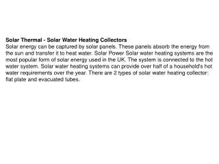
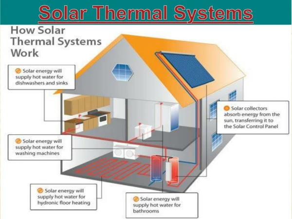
How Does Solar Thermal Work? • The sun’s rays hits a solar collector, heating the fluid inside. • The heated fluid in the collector passes through a heat exchanger, which transfers its heat energy to the surrounding potable water. • If an internal or external heat exchanger is not available, the heated collector fluid goes directly into the potable water in the tank.
Solar Fraction (SF) • One way of expressing the thermal performance of a solar system is by stating the percentage of the load met by solar energy on a month-by-month basis. • Monthly totals can be combined to yield the annual solar fraction, expressed as a decimal percentage (e.g. 0.15 = 15%) • If a solar system has a SF of 0 then there is no solar energy utilized. If it has a SF of 1.0 then all energy provided is from solar. • Dependent on many factors such as load, collector size, climate, etc. • Example, the same solar equipment installed in a home in Arizona may have a SF of 75%, but if installed in Connecticut, it may only have a SF of 30%.
System Types • Active is when a circulator pushes the fluid. • Passive is when water temperature difference moves the water. Hot water rises/cold water falls. • Open loop is when the potable water goes through the collector to be heated. • Closed loop is when the heating fluid is closed off from the potable water and is contained in a loop.
Solar Rating • The Solar Rating and Certification Corporation (SRCC) was provides independent testing, rating and certification of active solar collectors and solar domestic water heating systems. • Standard OG-100 “Operating guidelines for certifying solar collectors” • Standard OG-300 “Operating guidelines and minimum standards for certifying solar water heating systems”
OG-300 Certification • Standard OG-300 combines the physical testing of collectors and all major components in a solar water-heating system proposed for sale by manufacturer. • The standard also provides simulated performance estimates for that system in specific geographical locations. • Once a water heater is OG-300 certified, it then becomes ENERGY STAR® certified.
Solar Thermal System Components • Storage Tank • Stores and delivers heated potable water. • Collectors • Flat Panel; more efficient in warmer climates • Evacuated Tube; more efficient in colder climates • Circulation • Circulators • Controls • Thermistors • Fluid - the more glycol in the system, the harder the circulator works and lower the heat transfer capability.
Heat Exchange Coil • Vitraglas® lined, 1 ½” O.D. carbon steel coil. • Single Wall provides greater heat transfer. • Double Wall provides additional protection from heating fluid and surrounding water. • Because of the large diameter, a smaller and lower cost pump can be installed. • Smooth internal surface area limits the amount of mineral deposit, which could decrease heat transfer capabilities. • Glycol and toxicity rating of 1 (practically non-toxic) fluid can be introduced into coil.
Heat Exchange Coil • 1” NPT female fittings on single wall • ¾” NPT female fitting on double wall • The coil has a heat transfer area of 14.2 sq ft • Stored water volume of 2.7 gallons • Because of the material and thickness of the coil, maximum supply temperature from a heatingsource can be upwards of 240°F • Maximum supply temperature from a heatingsource must not exceed 250 F
Heat Exchange Coil Double Wall Single Wall
Head Loss • Head loss due to friction of water flowing in a pipe is determined in feet of head. As water moves through pipe and fittings, it loses energy to friction. Pumps or circulators provide the energy to make up for this loss “head loss” through the system. • The more water you push through the pipes, or the smaller the pipes are, the higher the head loss will be. • Higher head loss means larger more expensive pumps.
Integrated Mixing Device Package • Integrated Mixing Device Features: • Push to turn hand wheel prevents accidental temperature change. • Included thermo-strip to approximate outlet water temperature. • Allows water in the tank to be stored at higher temperatures, increasing usable hot water by as much as 50%, while controlling the hot water outlet at lower temperatures. • Additional outlet piping connection to draw off unmixed tank temperature water. • Additional intlet piping connection for recirculation water into the mixing device. • Additional outlet piping connection to draw off cold water without installing a saddle valve. • Teflon® coated internal components to extend product life.
Integrated Mixing Device* Stainless SteelFlexible Connector Mixed Hot Water Outlet Cold Water Inlet ½” NPT Un-Mixed Hot Water Outlet ¼” NPT Cold Water Outlet Push to TurnHand Wheel ½” NPT Recirculation Inlet *ASSE and UPC (IAPMO) Certified
Push to Turn Hand Wheel Graduation marks to allow easy adjustment. Each increment is 5ºF. Arrow is approximately 120°F 100°F to 145ºF Temperature Range
Solar Saver® Models • Models available • No heat exchanger; potable water is circulated through the solar collector. Suitable for frost free locations. • Single (upper) heating element • Supplied thermistor wires • Connections • Potable -- Inlet dip tube; Anodic outlet device • Solar – Dip tubes in top of water heater • Alternate side connects in 80 & 120 gallon models. • Solar sensor can be mounted by means of threaded stud.
EcoStor™ Solar Indirect Models • Models available • Single Wall Heat Exchanger for increased performance • Double Wall Heat Exchanger for additional protection between the heating fluid and potable water. • Single (upper) or Dual Incoloy elements • 4.5 or 5.5 kW elements. • Integrated Mixing Device for piping flexibility • Supplied thermistor wires • Two Anodes
Heat Exchanger Backup • Models available • Single Wall Upper Heat Exchanger • Double Wall Lower Heat Exchanger • Dual Heat Exchanger Design • Can be connected to a variety of different heating systems. • Solar, space heating, geothermal heating, boiler heating • Integrated Mixing Device • Supplied thermistor wires • Two Anodes
EcoStor2™ Gas Backup • Models Available • Natural Gas or Propane Gas • Atmospheric Vent • Double Wall Heat Exchanger • 61,000 – 76,000 BTU/hr. input range • Honeywell Self Diagnostic Gas Control • Advanced temperature control system • Intelligent diagnostics • Integrated Mixing Device • Supplied thermistor wires • Two Anodes
EcoStor2™ Specification Data Propane models feature a Titanium Stainless Steel Propane Burner. For propane (LP) models, change suffix “BN” to “SX”.
EcoStor2™ Gas Backup • Models Available • Natural Gas or Propane Gas • Power Vent (3” or 4” PVC, CPVC, ABS) • Double Wall Heat Exchanger • 60,000 – 76,000 BTU/hr. input range • Honeywell Self Diagnostic Electronic Gas Control • Advanced temperature control system • Intelligent diagnostics • Optional Programmable Setback Control • Integrated Mixing Device • Supplied thermistor wires • Two Anodes
EcoStor2™ Specification Data Propane models feature a Titanium Stainless Steel Propane Burner. For propane (LP) models, change suffix “BN” to “SX”.
EcoStor2™ Gas Backup • Models Available • Natural Gas Only • Atmospheric Vent • Double Wall Heat Exchanger • 40,000 – 55,000 BTU/hr. input range • Ultra Low NOx radiant burner • Meets the most stringent air quality requirements for allowable NOx emissions in the country • Honeywell Self Diagnostic Gas Control • Advanced temperature control system • Intelligent diagnostics • Integrated Mixing Device • Supplied thermistor wires • Two Anodes
How Do I Size a System?Water Demand • Determine the Daily Hot Water Demand (Gal.) • If unknown, estimate 30 gallons per person per day. • Determine typical inlet water temperature (°F) and desired outlet temperature (°F). • Calculate the amount of Btu’s needed per day. • BTU = Gallons x 8.25 x (Outlet – Inlet) • Example: 4 people with 58°F inlet with a 125°F tank • 4 people x 30 gallons/day = 120 gallons per day • BTU = 120 x 8.25 x (125-58) = 66,330 Btu/day
How Do I Size a System?Collector Demand • Flat panel – (Btu/day/1,000) x 1.1 = ft.2 of area. • More efficient in warmer climate/summer. • Evacuated Tube – (Btu/day/1,000) x 1.3 = ft.2 of area. • More efficient in cooler climate/winter. • Collector temperature - outside temperature is larger. • Calculate the amount of collector surface area. • Flat Panel: (66,330 Btu/day/1,000) x 1.1 = 73.0 ft2. • Evacuated Tube: (66,330 Btu/day/1,000) x 1.3 = 86.2 ft2. • Other variables exist such as climate and panel location