Download

1 / 24
240 likes | 260 Views
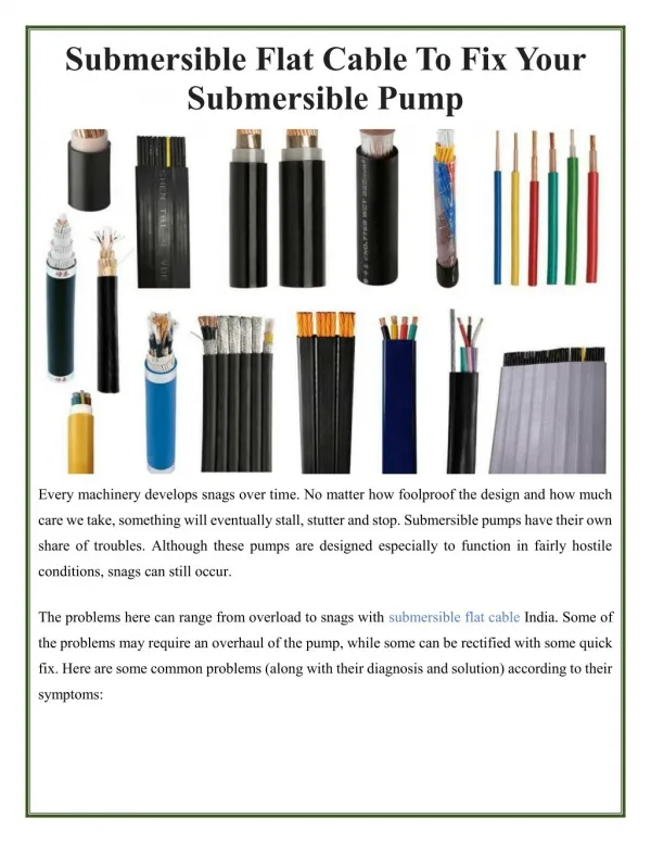
Hydromanu00ae TSQ Submersible Sand Pumps are a world's standard submersible agitator pump, Capable of transporting up to 70% solids, this pump is born to dredge and has earned itself a 'solids-handling' reputation for reliability and durability in the world's toughest applications, The wear parts are made from high chrome alloy, It is widely used in pumping sand, sludge, gravel, stone, mud, ore slurry, coal slurry, sand-stones containing big solid particles etc.

E N D
SAFETY WARNING The following warnings should be carefully read before operation. 1. The pump set must be well grounded. 2. Before starting up the pump, oil chamber must be filled with enough turbine oil. 3. Before starting up the pump, cold insulation resistance of the motor should not be lower than 50MΩ. 4. The cable should be in proper tightness to protect the cable from force damage. 5. Make sure the pump operate in correct direction. (This pump should rotate in clockwise direction looking down from the motor).
I. Product Introduction I.I Overview TSQ submersible slurry pump is hydraulic machinery, the motor and the pump of which are coaxially submerged in medium to work. The overflowing parts of the pump are made from high alloy wear-resistant material, so the pump has good wear resistance and large flowing passage. It is applicable for conveying media such as sludge, ore slurry, coal slurry, sandstones containing big solid particles. The product is designed and manufactured by domestic and over sea advanced technologies. Besides the main impeller, the bottom of the pump is additionally provided with a set of agitation impeller which can spray the deposited sludge into turbulent flow, and therefore the pump realizes high-concentration conveying under the condition of no auxiliary device. The unique seal device can effectively balance the pressure inside and outside the oil chamber, so as to project the reliability of
the mechanical seal to the maximum extent. The motor adopts various protective such as overheat protection, water inlet detecting projection, and can operate safely for a long term in harsh working conditions. The pump is applicable for pumping sand for building, silty sand, silt, tailing slurry, ore, iron sand ore, sediment in sewage treatment works, etc. I. II Structural Property The whole machine is dry submersible pump, and the motor adopts oil chamber seal mode and is provided with mechanical seal inside, so that high pressure water and impurities and are effectively prevented from entering inner cavity of the motor. 1. Besides the main impeller, there is the agitation impeller which can agitate the sludge deposited on the water bottom into turbulent flow and pump the sludge out. 2. The trans-flux parts such as the impeller and the agitation impeller are made from high-hardness high chromium cast steel, have wear resistance, corrosion resistance and strong drainage capacity, and allow big solid particles to pass. 3. The motor is submerged in water, is not limited by suction stroke, and has high sludge suction rate and thorough desilting. 4. The integral device is simplified, needs no auxiliary stirrer device or ejector device, and has simple and convenient operation and low total investment of the unit. 5. The agitation impeller directly approaches the depositional surface, and controls the concentration through submerged depth. Under the condition of large medium proportion, an auxiliary device can be arranged to increase the concentration of the medium. I. III Use Conditions 1. The power source is three –phase alternating-current supply, and thecapacity of the substation transformator two to three times of the rated capacity of themotor. 2. The temperature of the medium cannot exceed 60℃, and the medium does not contain inflammable or explosive gases.
3. The maximum weight concentration of the solid particles in the medium: the maximum weight concentration of the ash is 45% and maximum weight concentration of the slag is 60%. 4. The submerged depth of the unit is not more than 20 meters, and the minimum submerged depth takes submerging of the motor as reference. 5. The unit works in the medium vertically, and the working status is continuous. II. Production Selection TSQ submersible slurry pump has many specifications to meet different working conditions of different users. As long as specifications and modes meeting the working conditions are reasonably and correctly selected, the best benefit can be obtained with less investment, simultaneously, reasonable working conditions can effectively prolong the service life of the pump, and the methods are as follows: 1. Where the field conditions (such as voltage, frequency, water quality, power source and capacity) accords with the use conditions is mastered. 2. The pump specification is selected: 1) Initial selection of the flow rate : the flow rate of the pump is determined according to demands. 2) Determination of pipes: critical sedimentation flow velocity is calculated according to the conveyed medium, so as to reasonably select the pipe diameter. 3) Calculation of pip loss: the pipe loss is calculated according to the length of the pipe and the number of the siphons and valves. 4) Calculation of the pipe lift: the pump lift= vertical height difference from the water surface to the water outlet +pipe loss +outlet pressure+ safety margin(10%) 5) The pump specification is determined according to the pump lift and flow rate. 6) The installation mode is determined: fixed mode and mobile mode. 3. Friendly Tips
1) Only closed system has outlet pressure, and the outlet pressure of the open system is zero. 2) The power of the matched motor of the pump is calculated according to intermediate concentration (the medium density is 1.3.), and the power should be rechecked when the pump is used for high-concentration conveying. 3) When the medium cannot submerge the motor or the temperature of the medium is more than 60℃, cooling water is 5-8m3/h. 4) The outlet of the pump should be provided with a valve, when the pump is started, the valve should be closed and then the motor is started, and the valve is gradually opened after the motor normally rotates. 5) The valve should be closed first and then the power source is cut off when the pump is shut down, so as to prevent water hammer in the pipe from severely damaging the pump. 6) In order to prevent blockage of the pipe, clear water should be conveyed for a while to clean the pipe before machine halt, until clear water flows out from the water outlet. III. Model significance TSQ 200 -- 15 -- 22 Motor power (Kw) Rated head (m) Rated flow (m3/h) Model: TSQ
IV. Performance parameter Biggest particles allow to pass (mm) DISCH. DIA (mm) Rotation speed (r/min) Weight CAP (m³/h) Head (m) Power (kw) Eff. (%) NO. Pump Type (Kg) 1 TSQ20-15-3 65 20 15 3 1460 43 10 110 2 TSQ15-20-3 65 15 20 3 1460 43 10 110 3 TSQ25-15-3 65 25 15 3 1460 43 10 110 4 TSQ30-10-4 65 30 10 4 1460 43 10 120 5 TSQ20-25-4 65 20 25 4 1460 43 10 120 6 TSQ25-20-4 65 25 20 4 1460 43 10 120 7 TSQ50-10-5.5 80 50 10 5.5 1460 43 13 130 8 TSQ45-15-5.5 80 45 15 5.5 1460 43 13 130 9 TSQ15-20-5.5 80 15 20 5.5 1460 43 13 130 24 30 36 35 50 60 35 50 60 70 100 120 18 25 30 35 50 60 31 30 29 22 21 20 29 26 24 20 18 15 41 40 39 38 35 32 10 TSQ30-30-7.5 80 7.5 1460 43 13 140 11 TSQ50-21-11 100 11 1460 48 21 200 12 TSQ50-26-11 80 11 1460 48 13 200 13 TSQ100-18-11 100 11 1460 55 21 260 14 TSQ25-40-15 80 15 1460 35 13 400 15 TSQ50-35-15 100 15 1460 47 13 400
Biggest particles allow to pass (mm) DISCH. DIA (mm) Rotation speed (r/min) Weight CAP (m³/h) Head (m) Power (kw) Eff. (%) NO. Pump Type (Kg) 42 60 72 52 75 90 105 150 33 30 27 28 25 22 17 15 16 TSQ60-30-15 100 15 1460 50 13 270 17 TSQ75-25-15 100 15 1460 51 13 270 18 TSQ150-15-15 150 15 1460 56 21 300 180 13 52 75 90 70 100 120 105 150 180 140 200 240 70 100 120 105 150 180 140 200 240 175 250 300 38 35 32 27 25 22 25 22 20 17 15 13.5 38 35 31 33 30 26 28 25 21 23 20 18 19 TSQ75-35-22 100 22 980 48 13 700 20 TSQ100-25-22 100 22 980 55 14 700 21 TSQ150-22-22 150 22 980 60 32 700 22 TSQ200-15-22 150 22 980 60 45 700 23 TSQ100-35-30 100 30 980 50 21 660 24 TSQ150-30-30 150 30 980 50 21 660 25 TSQ200-25-30 150 30 980 51 25 660 26 TSQ250-20-30 150 30 980 60 25 660
Biggest particles allow to pass (mm) DISCH. DIA (mm) Rotation speed (r/min) Weight CAP (m³/h) Head (m) Power (kw) Eff. (%) NO. Pump Type (Kg) 70 100 120 70 100 120 240 300 360 70 100 120 140 200 240 105 150 180 175 250 300 210 300 360 420 600 720 105 150 180 105 150 180 140 200 240 48 45 42 53 50 47 22 20 17 64 60 55 33 30 27 47 45 42 38 35 33 34 30 26 18 15 11 58 55 51 63 60 56 48 45 41 27 TSQ100-45-37 100 37 980 43 21 1020 28 TSQ100-50-37 100 37 980 43 13 1020 29 150 37 980 58 28 930 TSQ300-20-37 30 TSQ100-60-45 100 45 980 43 13 1200 31 TSQ200-30-45 150 45 980 53 25 1200 32 TSQ150-45-55 150 55 980 50 21 1370 33 TSQ250-35-55 150 55 980 53 36 1370 34 TSQ300-30-55 150 55 980 55 36 1370 35 TSQ600-15-55 250 55 980 62 32 1370 36 TSQ150-55-75 150 75 980 48 15 1848 37 TSQ150-60-75 150 75 980 48 15 1848 38 TSQ200-45-75 150 75 980 52 18 1848
Biggest particles allow to pass (mm) DISCH. DIA (mm) Rotation speed (r/min) Weight CAP (m³/h) Head (m) Power (kw) Eff. (%) NO. Pump Type (Kg) 140 200 240 245 350 420 280 400 480 140 200 240 170 250 300 210 300 360 210 300 360 280 400 480 350 500 600 315 450 540 175 250 300 210 300 360 58 55 51 38 35 31 29 25 23 63 60 57 58 55 52 50 45 39 54 50 45 44 40 36 30 25 20 34 30 25 64 60 55 64 60 56 39 TSQ200-55-75 150 75 980 50 18 1848 40 TSQ350-35-75 200 75 980 60 29 1860 41 TSQ400-25-75 200 75 980 62 29 1860 42 TSQ200-60-90 150 90 980 50 14 1860 43 TSQ250-55-90 150 90 980 50 14 1860 44 TSQ300-45-90 150 90 980 52 25 1860 45 TSQ300-50-90 150 90 980 52 25 1860 46 TSQ400-40-90 200 90 980 53 25 1860 47 TSQ500-25-90 200 90 980 65 25 1860 48 TSQ450-30-90 200 90 980 64 25 1860 49 TSQ250-60-110 150 110 980 54 18 2370 50 TSQ300-60-110 150 110 980 55 18 2370
Biggest particles allow to pass (mm) DISCH. DIA (mm) Rotation speed (r/min) Weight CAP (m³/h) Head (m) Power (kw) Eff. (%) NO. Pump Type (Kg) 280 400 480 350 500 600 420 600 720 560 800 960 700 1000 1200 545 780 935 280 400 480 350 500 600 350 500 600 560 800 960 700 1000 1200 875 1250 1500 54 50 45 38 35 31 33 30 26 28 25 21 22 18 13 29 26 22 64 60 55 49 45 42 59 55 52 38 35 32 27 22 17 18 15 12 51 TSQ400-50-110 200 110 980 56 28 2370 52 TSQ500-35-110 200 110 980 61 32 2370 53 TSQ600-30-110 250 110 980 64 35 2370 54 TSQ800-25-110 300 110 980 66 50 2370 55 TSQ1000-18-110 300 110 980 68 50 2370 56 TSQ780-26-110 300 110 980 68 50 2370 57 TSQ400-60-132 200 132 980 68 28 2400 58 TSQ500-45-132 200 132 980 67 28 2400 59 TSQ500-55-132 200 132 980 70 28 2400 60 TSQ800-35-132 300 132 980 70 42 2400 61 TSQ1000-22-132 300 132 980 71 50 2400 62 TSQ1250-15-132 300 132 980 70 56 2400
Biggest particles allow to pass (mm) DISCH. DIA (mm) Rotation speed (r/min) Weight CAP (m³/h) Head (m) Power (kw) Eff. (%) NO. Pump Type (Kg) 420 600 720 455 650 780 875 1250 1500 700 1000 1200 1225 1750 2100 420 600 720 560 800 960 700 1000 1200 1050 1500 1800 1400 2000 2400 560 800 960 875 1250 1500 56 50 43 56 52 44 28 25 22 34 30 25 19 15 10 59 55 50 49 45 40 45 40 35 24 20 15 25 26 14 60 55 50 39 35 30 63 TSQ600-50-160 200 160 980 65 28 3180 64 TSQ650-52-160 200 160 980 65 28 3180 65 TSQ1250-25-160 350 160 980 70 56 3180 66 TSQ1000-30-160 300 160 980 70 53 3180 67 TSQ1750-15-185 350 185 980 70 56 3180 68 TSQ600-55-200 250 200 980 62 28 4080 69 TSQ800-45-200 300 200 980 66 42 4080 70 TSQ1000-40-200 300 200 980 70 42 4080 71 TSQ1500-20-200 350 200 980 71 56 4080 72 TSQ2000- 20-200 400 200 980 72 56 4080 73 TSQ800-55-220 300 220 980 66 38 4080 74 TSQ1250-35-220 350 220 980 70 45 4080
Biggest particles allow to pass (mm) DISCH. DIA (mm) Rotation speed (r/min) Weight CAP (m³/h) Head (m) Power (kw) Eff. (%) NO. Pump Type (Kg) 700 1000 1200 1050 1500 1800 1225 1750 2100 1050 1500 1800 1225 1750 2100 1400 2000 2400 55 50 45 40 35 30 34 30 25 45 40 35 45 40 35 40 35 30 75 TSQ1000-50-250 300 250 980 68 45 4200 76 TSQ1500-35-250 350 250 980 72 50 4200 77 TSQ1750-30-250 350 250 980 70 55 4200 78 TSQ1500-40-280 350 280 980 70 50 4200 79 TSQ1750-40-315 350 315 980 70 55 4200 80 TSQ2000-35-315 400 315 980 72 60 4440
V. Outline dimension L L1 (mm) 720 720 720 720 720 720 L2 (mm) 290 290 290 290 290 290 A B C d No Model (mm) 800 800 800 800 800 800 (mm) 480 480 480 480 480 480 (mm) 320 320 320 320 320 320 (mm) 350 350 350 350 350 350 (mm) 65 65 65 65 65 65 1 2 3 4 5 6 TSQ20-15-3 TSQ15-20-3 TSQ25-15-3 TSQ30-10-4 TSQ20-25-4 TSQ25-20-4
L L1 (mm) 700 700 700 700 738 720 738 774 774 774 774 814 1105 1135 1110 1110 1144 1144 1148 1148 1170 1170 1170 1230 1255 1248 1255 1255 1275 1380 1380 1425 1380 1404 1410 1380 1380 L2 (mm) 296 296 296 296 300 296 300 290 290 290 300 340 502 535 507 507 425 425 469 469 485 485 510 495 495 488 495 495 515 482 482 488 482 485 485 482 482 A B C d No Model (mm) 842 842 842 842 913 889 913 950 950 950 950 990 1370 1401 1375 1375 1452 1452 1460 1460 1560 1560 1567 1670 1699 1692 1699 1699 1720 1835 1835 1904 1835 1883 1888 1835 1835 (mm) 605 605 605 605 606 605 606 673 632 632 606 620 925 883 870 870 832 832 835 835 950 950 1070 1050 1006 1011 1006 1006 1052 1115 1115 1011 1115 1332 1422 1115 1115 (mm) 390 390 390 390 406 390 406 440 385 385 406 410 650 630 630 630 630 630 630 630 650 650 595 680 665 678 665 665 711 800 800 678 800 690 665 800 800 (mm) 396 396 396 396 405 396 405 435 422 422 405 455 505 545 551 551 605 605 605 605 640 640 775 665 650 640 650 650 675 715 715 640 715 947 1047 715 715 (mm) 80 80 80 80 80 100 80 100 80 100 100 100 150 100 100 100 150 100 150 150 150 100 150 100 100 150 150 150 150 250 150 150 150 150 200 200 150 7 8 9 10 11 12 13 14 15 16 17 18 19 20 21 22 23 24 25 26 27 28 29 30 31 32 33 34 35 36 37 38 39 40 41 42 43 TSQ50-10-5.5 TSQ45-15-5.5 TSQ15-20-5.5 TSQ30-30-7.5 TSQ50-21-11 TSQ50- 26-11 TSQ100-18-11 TSQ25-40-15 TSQ50-35-15 TSQ60-30-15 TSQ75-25-15 TSQ150-15-15 TSQ75-35-22 TSQ100-25-22 TSQ150-22-22 TSQ200-15-22 TSQ100-35-30 TSQ150-30-30 TSQ200-25-30 TSQ250-20-30 TSQ100-45-37 TSQ100-50-37 TSQ300-20-37 TSQ100-60-45 TSQ200-30-45 TSQ150-45-55 TSQ250-35-55 TSQ300-30-55 TSQ600-15-55 TSQ150-55-75 TSQ150-60-75 TSQ200-45-75 TSQ200-55-75 TSQ350-35-75 TSQ400-25-75 TSQ200-60-90 TSQ200-55-90
L L1 (mm) L2 (mm) A B C d No Model (mm) (mm) (mm) (mm) (mm) 44 45 46 47 48 49 50 51 52 53 54 55 56 57 58 59 60 61 62 63 64 65 66 67 68 69 70 71 72 73 74 75 76 77 78 79 80 TSQ300-45-90 TSQ300-50-90 TSQ400-40-90 TSQ500-25-90 TSQ450-30-90 TSQ250-60-110 TSQ300-60-110 TSQ400-50-110 TSQ500- 35-110 TSQ600- 30-110 TSQ800- 25-110 TSQ1000-18-110 TSQ780-26-110 TSQ400-60-132 TSQ500-45-132 TSQ500-55-132 TSQ800-35-132 TSQ1000-22-132 TSQ1250-15-132 TSQ600-50-160 TSQ650-52-160 TSQ1250-25-160 TSQ1000-30-160 TSQ1750-15-185 TSQ600-55-200 TSQ800-45-200 TSQ1000-40-200 TSQ1500-20-200 TSQ2000-20-200 TSQ800-55-220 TSQ1250-35-220 TSQ1000-50-250 TSQ1500-35-250 TSQ1750-30-250 TSQ1500-40-280 TSQ1750-40-315 TSQ2000-31-315 1883 1922 1940 1888 1888 2203 2203 2225 2245 2245 2407 2407 2407 2328 2320 2320 2538 2465 2538 2673 2673 2890 2891 2900 2673 2934 2934 3060 3060 2934 2922 2980 3012 3012 3058 3235 3235 1380 1420 1430 1410 1410 1527 1527 1550 1570 1570 1725 1725 1725 1665 1656 1656 1784 1801 1784 1772 1772 1990 2137 2140 1772 1993 1993 2049 2049 1993 2021 2081 2111 2111 2159 2261 2261 482 490 500 485 485 485 485 500 520 520 626 626 626 520 472 472 601 626 601 472 472 672 601 652 472 710 710 672 672 710 730 710 730 730 710 804 804 1115 1540 1580 1422 1422 1115 1115 1190 1180 1180 1640 1640 1640 1540 1124 1124 1581 1640 1581 1124 1124 1600 1581 1660 1140 1686 1686 1770 1880 1686 2150 2250 2150 2150 2250 2180 2260 800 849 850 665 665 800 800 760 750 750 854 854 854 849 823 823 802 854 802 823 823 820 802 820 823 900 900 870 870 900 977 9987 977 977 9987 1026 1026 715 1110 1150 1047 1047 715 715 790 1020 1020 1027 1207 1207 1117 739 739 1177 1207 1177 739 739 1180 1177 1260 739 1229 1229 1850 1896 1229 1630 1730 1630 1630 1730 1650 1730 150 150 150 200 200 200 150 150 200 200 250 300 300 300 200 200 200 300 300 300 200 200 350 300 350 250 300 300 350 400 300 350 300 350 350 350 400
VI. Installation and Application Instruction 1. Preparation before Installation 1) Carefully check whether the electric pump is deformed or damaged in the processes of transport, storage and installation and whether the fastening pieces and loosened or fallen off before starting. 2) Check whether the cable is damaged or broken, if yes, replace the cable to avoid electric leakage. 3) Check whether the power source device is safe and reliable and that the rated voltage should accord with the nameplate. 4) Use a megohmmeter to check that the motor stator winding cold ground insulation resistance should not be less than 50MΩ. 5) Check whether the oil quantity in the oil chamber is appropriate and that the oil level of the unit in the vertical position should be flush with the oil filling opening. 6) Make sure that clear cold water is filled continuously when the submersible pump with the cooling shield is started, and make sure that the outlet is smooth and the cooling water flows in from one side of the lower end and flows out from the upper end of the other side. 2. Notices After the pump is operated normally, please observe whether the voltage of the power source, the working current, the flow rate of the pump and the vibration of the pump are normal at any time. If one of the following conditions occurs, please immediately stop the machine to check: 1) The working current exceeds the rated current. 2) In the rated pump lift, the flow rate is reduced by more than 20% or the water outlet is discontinuous. 3) The voltage of the water power source is over high or too low. 4) The pump has obvious vibration or noise. 3. Installation Notices 1) Electrical connection: the electrical connection should be carried out by professional electrician according to the circuit diagram, the insulation resistance should be detected at any time in the installation process, and the motor insulation resistance should not be less than 50 MΩ after the installation is over. The pump is hung and subjected to inching turning, so as to observe its rotation direction, and the pump is rated clockwise if a person looks downward from the motor direction. If the rotation direction is wrong, please replace any two connectors of the three phase power supply. 2) Prohibit using the cable of the pump as a rope for installation and hoisting, so as to avoid dangers. 3) The pump should be vertically submerged in water, should not be horizontally placed and fall into sludge, and the power source should be cut off when the pump is moved. 4. Storage Notices
1) The electric pump should be placed into clear water to rotate for several minutes after being used for many times, so as to prevent sediment from remaining in the pump and ensure the cleanness of the electric pump. 2) The electric pump should be taken out from water if not used for a long term, so as to reduce the occasion that the motor stator winding is affected with damp and prolong the service life of the electric pump. 3) Under normal working conditions, the electric pump should be maintained after working for a year, the worn wearing parts should be replaced, the tightening status should be checked, and the lubricating grease of the bearing and the insulating oil in the oil chamber should be replenished or replaced, so as to ensure good operation of the electric pump. VII. Field installation and use of examples
VIII.Causes of Faults and Countermeasures NO. Faults Possible Causes Solution 1.The pump is friction-resistant 2.The pump lift of the device is too low and the pump is operated in large flow rate 1.Adjusting the clearance 2. Controlling the flow rate by the valve or replacing a pump with proper pump lift 3.Replacing the bearing The Current is over high and exceeds the rated current 1 3. The bearing is damaged
1. The voltage is too low 1. Adjusting the voltage to the rated value 2. The motor is rotated with single phase 2.Checking the lines and connecting the broken lines 3.Removing the foreign matters The motor does not rotate and has noise when started. 2 3. The pump is blocked by foreign matters 4.The impeller rubs with the inner pump over or the water suction plate 1.The impeller rotates reversely 4.Adjusting the clearance of the impeller to normal value 1.Changing any two phase power cords 2.Water strainer is blocked 2. Removing the blockage The pump does not output water or output a small quantity of water 3.The water inlet is exposed out of the water surface 3.Adjusting the pump to submerged the pump 3 4.Water pipe leaks or are leaked 4.Replacing the water pipe or removing the sludge Selecting a pump with proper pump lift 5.The actual pump lift is too high 1.Cable connector is damaged 1.treating the cable connector again 2.The stator winding insulation is damaged 2.Replacing the stator winding The insulation resistance is reduced to below 0.5 MΩ 4 3.Water enters the cavity of the motor 3.removing the water content and drying the winding 4.repairing the cable 4.The cable is damaged 1.The impeller is worn seriously 1.Replacing the impeller The pump has unstable operation and serious vibration 2.Impurities block the rotating parts 2.Clearing the impurities 5 3. The bearing is damaged. 3.Replacing the bearing
IX. Electrical wiring diagram The cable for the pump is 4 cores, 3 pieces power line, and one is for earth wire; The pump which with protective device also with control cable; There is different signboard for difference core wire with difference function. The cable core wire to the grounding wire insulation resistance Cable length Type Symbol Core name Core function Control of three-phase power core Three phase power core ∞ U、V、W Power cable 10 m For grounding wire Connected to ground Together with hull Thermal protection wire To the thermal protector WC 0 Control cable 10 m Leakage protection wire To the float switch ∞ XL X. Maintenance and repair 1. If the pump needs no longer to use, please take it out of the water, make its surface clean, remove debris of filter screen, paint anti-rust oil, and then put it on the dry ventilated place. 2. After continuously or totally operating more than 2500 hours, the fasteners and seal of pump should be checked, the turbine oil and mechanical seal of oil chamber should be changed. 3. After continuously operating for one year, these wearing parts should be exchanged: mechanical seal, oil seal, impeller, stirring impeller, inner pump cover, water suction plate. etc. 4. After being re-disassembled, the inner chamber of motor and oil chamber must be made pressure test of 0.2Mpa, no leakage happens within 5 minutes.
XI. Complete sets of products &Wearing parts accessories Quantity (piece) Item Name Remark With 10 meter length cable (Rated length is 10 meter, if need longer, please inform before order) Submersible slurry pump 1 Completed products Control box 1 With rubber mat and connecting bolts Hose connecter 1 Pump case Impeller agitator It can be purchased separately according to customers’ requirements Inner pump cover Wearing parts Suck-water plate Mechanical seal Hose connecter Oil seal