Download
1 / 12
140 likes | 310 Views
Synthesis For CMOS/PTL Circuits. Congguang Yang Maciej Ciesielski Dept. of Electrical & Computer Engineering University of Massachusetts, Amherst. Sponsored by NSF. Motivation. Traditional logic synthesis (SIS) use factored forms, algebraic factorization: a(b+c)

E N D
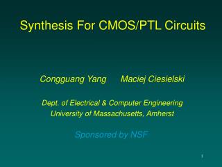
Synthesis For CMOS/PTL Circuits Congguang Yang Maciej Ciesielski Dept. of Electrical & Computer Engineering University of Massachusetts, Amherst Sponsored by NSF
Motivation • Traditional logic synthesis (SIS) • use factored forms, algebraic factorization: a(b+c) • boolean formulas treated as polynomials: F = ac + bc + ad + bd = (a + b) (c + d) • weak Boolean factorization capability F = a + bc = (a + b)(a + c) …. cannot be found easily • good for AND/OR, difficult to identify XOR and MUX logic • Our approach • based on BDD representation of logic • truly Boolean operations, Boolean algebra rules applied: a + a = a, a * a’ =0, a * 1 = a, a * 0 = 0, etc • can easily identify XOR, MUX structures • very fast
BDD-based Logic Decomposition • Observation: • BDD structure reveals functional decomposition. • Simple dominators • Algebraic AND, OR, XOR decomposition • Generalized dominators • Boolean AND, OR, XOR decomposition • Cofactor, single/super node • Simple/complex MUX • Identify Dominators (BDD structures) • different logic decompositions
F = a + bc a D = a + b Q = a + c b a a c b c 0 0 0 1 1 1 Boolean AND/OR decomposition F = a + bc = (a + b)(a + c) = *
D = af + b + c Q F D D a a a a f f b b b reduce f f c c c b b b b 0 0 1 0 1 c c c c g Q d a e minimize g g 1 0 0 d d e e 1 0 1 0 DC DC Boolean AND decomposition - example F = D Q Q = ag + d + e 1. Find a cut in BDD of F 2. Create divisor D (generalized dominator), reduce D 3. Compute Q from F, minimize Q
XOR Decomposition – Role of X-dominator General idea: • Identify a node (x-dominator) with complement and regular edges • Split node function into f and f’ • Compose the two parts with XOR
MUX Decomposition F F 0 1 v v 0 1 g g f f F F a a c d b b c d 0 1 0 1 Complex MUX SimpleMUX • Identify exactly two nodes covering all paths to 1, 0 • Connect one node to 1, the other to 0 • Upper portion defines control h
Decomposition of Multiple-output Functions • Build BDD for each output • Decompose each BDD • Construct factoring trees • Identify logic sharing
Application to CMOS/PTL Logic Synthesis • Logic balancing • Reduction of long transistor chains • Fanout reduction
Application to CMOS/PTL Logic Synthesis • Extract XOR’s and MUXes during BDD decomposition • Map the decomposed logic onto CMOS and PTL • Preserve XOR’s and MUXes for PTL • Use CMOS to provide buffering for PTL • New technology mapping techniques needed (tree-based mappers are inadequate) • Develop PTL cell library • (with and w/out buffers)
Preliminary Results – XOR Intensive Logic • Comparison with SIS and [tsai’96] • # XOR’s: after/before technology mapping • SIS mapper used (lower cost assigned to XOR gates)
Application to FPGA Synthesis • Very fast (orders of magnitude) • Good for rapid prototyping • Good results in terms of logic density and wiring • 30 – 40% improvement compared to SIS + FlowMap • Open problems: • Incremental synthesis • Specialized decomposition specifically for FPGAs