Download
1 / 15
150 likes | 169 Views
"ITEM: VM158A11AB313B<br>*Fieldbus, multipole or individually wired for installation flexibility<br>*Long life up to 100 million cycles<br>*Up to 32 solenoids (16 valves) in one valve island<br>*Compact and lightweight<br>*Integral push in fittings"<br>For More Information visit on our website:- www.instronline.com<br>Our E-mail Address:-info@instronline.com <br>

E N D
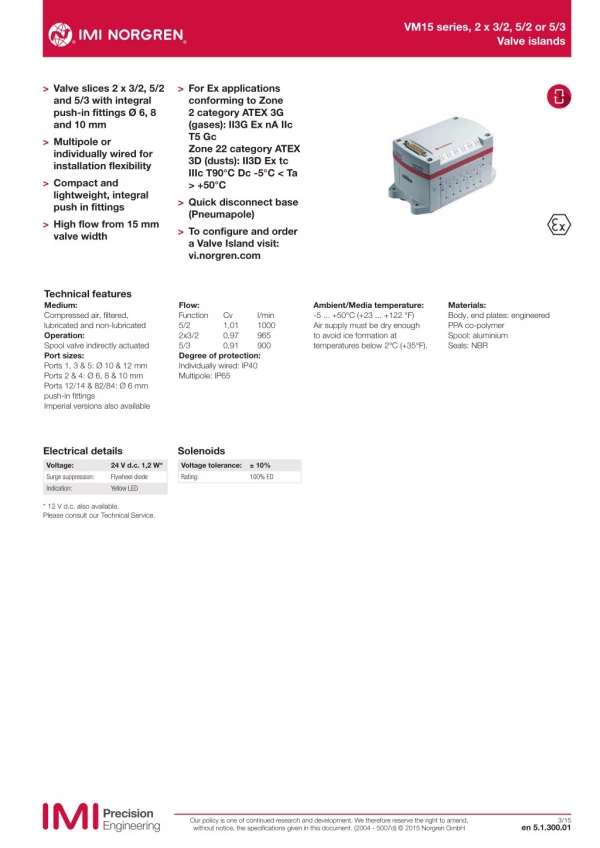
VM15 series, 2 x 3/2, 5/2 or 5/3 Valve islands > Valve slices 2 x 3/2, 5/2 and 5/3 with integral push-in fittings Ø 6, 8 and 10 mm > Multipole or individually wired for installation flexibility > Compact and lightweight, integral push in fittings > High flow from 15 mm valve width > For Ex applications conforming to Zone 2 category ATEX 3G (gases): II3G Ex nA IIc T5 Gc Zone 22 category ATEX 3D (dusts): II3D Ex tc IIIc T90°C Dc -5°C < Ta > +50°C > Quick disconnect base (Pneumapole) > To configure and order a Valve Island visit: vi.norgren.com Technical features Medium: Compressed air, filtered, lubricated and non-lubricated Operation: Spool valve indirectly actuated Port sizes: Ports 1, 3 & 5: Ø 10 & 12 mm Ports 2 & 4: Ø 6, 8 & 10 mm Ports 12/14 & 82/84: Ø 6 mm push-in fittings Imperial versions also available Flow: Function 5/2 2x3/2 5/3 Degree of protection: Individually wired: IP40 Multipole: IP65 Ambient/Media temperature: -5 ... +50°C (+23 ... +122 °F) Air supply must be dry enough to avoid ice formation at temperatures below 2°C (+35°F). Materials: Body, end plates: engineered PPA co-polymer Spool: aluminium Seals: NBR Cv 1,01 0,97 0,91 l/min 1000 965 900 Electrical details Solenoids Voltage: Surge suppression: Indication: 24 V d.c. 1,2 W* Flywheel diode Yellow LED Voltage tolerance: Rating: ± 10% 100% ED * 12 V d.c. also available. Please consult our Technical Service. Our policy is one of continued research and development. We therefore reserve the right to amend, without notice, the specifications given in this document. (2004 - 5007d) © 2015 Norgren GmbH 3/15 en 5.1.300.01
VM15 series, 2 x 3/2, 5/2 or 5/3 Valve islands Technical data 2 x 3/2 Double solenoid actuated valves Symbol Function Actuation Pilot supply Manual override Operating pressure (bar) Pilot pressure (bar) Weight (kg) Model 2 x 3/2 NC Solenoid/spring Internal Push and turn to lock 3 ... 8 – 0,10 VM15*A11AB213B 410 2 14 10 12 2 x 3/2 NC Solenoid/spring Internal Push only 3 ... 8 – 0,10 VM15*A11AB313B 84 82 5 1 3 2 x 3/2 NC Solenoid/spring External Push and turn to lock -0,9 ... 8 3 ... 8 0,10 VM15*A22AB213B 410 2 14 10 12 2 x 3/2 NC Solenoid/spring External Push only -0,9 ... 8 3 ... 8 0,10 VM15*A22AB313B 84 82 14/12 5 1 3 2 x 3/2 NO Solenoid/spring Internal Push and turn to lock 3 ... 8 – 0,10 VM15*B11AB213B 414 2 10 12 10 2 x 3/2 NO Solenoid/spring Internal Push only 3 ... 8 – 0,10 VM15*B11AB313B 84 82 3 5 1 2 x 3/2 NO Solenoid/spring External Push and turn to lock -0,9 ... 8 3 ... 8 0,10 VM15*B22AB213B 414 2 10 12 10 2 x 3/2 NO Solenoid/spring External Push only -0,9 ... 8 3 ... 8 0,10 VM15*B22AB313B 84 82 14/12 5 1 3 2 x 3/2 NO/NC Solenoid/spring Internal Push and turn to lock 3 ... 8 – 0,10 VM15*C11AB213B 410 2 14 12 10 2 x 3/2 NO/NC Solenoid/spring Internal Push only 3 ... 8 – 0,10 VM15*C11AB313B 84 82 3 5 1 2 x 3/2 NO/NC Solenoid/spring External Push and turn to lock -0,9 ... 8 3 ... 8 0,10 VM15*C22AB213B 410 2 14 12 10 2 x 3/2 NO/NC Solenoid/spring External Push only -0,9 ... 8 3 ... 8 0,10 VM15*C22AB313B 84 82 14/12 5 1 3 5/2 Single and double solenoid actuated valves 14 Symbol Function Actuation Pilot supply Manual override Operating pressure (bar) Pilot pressure (bar) Weight (kg) Model 5/2 5/2 Solenoid/spring Solenoid/spring Internal Internal Push and turn to lock Push only 3 ... 8 3 ... 8 – – 0,09 0,09 VM15*517AB213B VM15*517AB313B 2 4 14 12 5 3 1 5/2 5/2 Solenoid/spring Solenoid/spring External External Push and turn to lock Push only -0,9 ... 8 -0,9 ... 8 3 ... 8 3 ... 8 0,09 0,09 VM15*527AB213B VM15*527AB313B 2 4 12 14 5 3 1 5/2 5/2 Solenoid/solenoid Solenoid/solenoid Internal Internal Push and turn to lock Push only 3 ... 8 3 ... 8 – – 0,10 0,10 VM15*511AB213B VM15*511AB313B 4 4 2 14 12 5 3 1 3 5/2 Solenoid/solenoid External Push and turn to lock -0,9 ... 8 2 ... 8 0,10 VM15*522AB213B 2 4 5/2 Solenoid/solenoid External Push only -0,9 ... 8 2 ... 8 0,10 VM15*522AB313B 14 12 5 3 1 5/3 Double solenoid actuated valves Function Actuation Pilot supply Manual override Operating pressure (bar) Pilot pressure (bar) Weight (kg) Model Symbol 5/3 APB 5/3 APB Solenoid/solenoid Solenoid/solenoid Internal Internal Push and turn to lock Push only 3 ... 8 3 ... 8 – – 0,10 0,10 VM15*611AB213B VM15*611AB313B 4 14 12 5 3 1 5/3 APB 5/3 APB Solenoid/solenoid Solenoid/solenoid External External Push and turn to lock Push only 0,9 ... 8 0,9 ... 8 3 ... 8 3 ... 8 0,10 0,10 VM15*622AB213B VM15*622AB313B 2 4 14 12 5 1 3 * For selection of port sizes please see page 3 Note: For 5/3 COE please use 2 x 3/2 NC. For 5/3 COP please use 2 x 3/2 NO APB = All Ports Blocked COE = Centre Open Exhaust COP = Centre Open Pressure Our policy is one of continued research and development. We therefore reserve the right to amend, without notice, the specifications given in this document. (2004 - 5007d) © 2015 Norgren GmbH en 5.1.300.02 3/15
VM15 series, 2 x 3/2, 5/2 or 5/3 Valve islands Option selector VM15˙˙˙˙AB˙13B Tube size 6 mm PIF 8 mm PIF 10 mm PIF No PIF (for use wi h Pneumapole) *1) Valve function 5/2 5/3 APB 2 x 3/2 NC and 5/3 COE 2 x 3/2 NO and 5/3 COP 2 x 3/2 NC and NO Substitute Manual override Turn to lock Push only Actuation/pilot supply Solenoid/solenoid internal pilot Solenoid/spring internal pilot *2) Solenoid/solenoid external pilot Solenoid/spring external pilot *2) Substitute 6 8 Y 7 2 3 Substitute 11 17 22 27 Substitute 5 6 A B C Note: For 5/3 COE and COP use 2 x 3/2 APB = All Ports Blocked COE = Centre Open Exhaust COP = Centre Open Pressure *1) Requires Pneumapole sub-base *2) Can only be used with 5/2 valve Our policy is one of continued research and development. We therefore reserve the right to amend, without notice, the specifications given in this document. (2004 - 5007d) © 2015 Norgren GmbH en 5.1.300.03 3/15
VM15 series, 2 x 3/2, 5/2 or 5/3 Valve islands Accessories Valve blanking station Port blanking station Intermediate supply and exhaust manifold (ISEM) Pneumapole sub-base Page 6 Page 6 Page 5 Page 10 & 11 VM156517AQ0300 VM156517AQ0301 (Port 1 blanked) VM156517AQ0302 (Ports 3 & 5 blanked) VM156517AQ0303 (Ports 1, 3 & 5 blanked) VM156517AQ0304 (Feed right) VM156517AQ0305 (Feed left) VM156517AQ0306 (Feed right and left) DIN Rail fixing kit DIN rail Label cover kit Labels V12022-K30 V10009-C00 (1 m) V12016-K30 (4 Station) V12016-K31 (6 Station) V12016-K32 (8 Station) V12016-K33 (10 Station) V12016-K34 (12 Station) V12016-K35 (16 Station) V12033-L01 (write and seal label) V12034-L01 (paper label) Pressure switch for pilot ports 12 and 14 Silencer Plug Page 11 Page 11 Page 11 VM106517AQ0806 (6 mm) T45P0006 (6 mm) T45P0008 (8 mm) T45P0010 (10 mm) T45P0012 (12 mm) C00040600 (6 mm) C00040800 (8 mm) C00041000 (10 mm) C00041200 (12 mm) D Sub-connector 44 pin, IP65 D Sub-connector 25 pin 90°, IP65 D Sub-connector 44 pin 90°, IP65 2 Pin connector IP40 D Sub-connector 25 pin, IP65 Page 9 Page 9 Page 10 Page 10 V11569-E01 (1 m) V11569-E03 (3 m) V11569-E05 (5 m) V11570-E01 (1 m) V11570-E03 (3 m) V11570-E05 (5 m) V12086-E01 (1 m) V12086-E03 (3 m) V12086-E05 (5 m) V12088-E01 (1 m) V12088-E03 (3 m) V12088-E05 (5 m) V11556-E03 (0,3 m) V11556-E03 (0,3 m) Our policy is one of continued research and development. We therefore reserve the right to amend, without notice, the specifications given in this document. (2004 - 5007d) © 2015 Norgren GmbH en 5.1.300.04 3/15
VM15 series, 2 x 3/2, 5/2 or 5/3 Valve islands Valve slices 2 x 3/2, 5/2 & 5/3 with integral push-in fittings - Ø 6, 8 or 10 mm Dimensions in mm Projection/First angle Dimensions Single solenoid Double solenoid 5/3 APB, double solenoid Blanking plates 14,7 14,7 14,7 14,7 93,5 93,5 93,5 7 93,5 9 9 63 63 63 63 36,5 20 36,5 20 Valve blanking station VM156517AQ0300 Port blanking station VM156517AQ0301 VM156517AQ0302 VM156517AQ0303 Short code Port 1 blanked Ports 3 & 5 blanked Ports 1, 3 & 5 blanked Weight (kg) 0,057 0,057 0,057 Intermediate supply and exhaust manifold (ISEM) VM156517AQ0304 VM156517AQ0305 VM156517AQ0306 1 3 14,7 14,7 14,5 3 5 93,5 93,5 93,5 63 63 63 ISEM Feed right Push IN fittings Ø 8 mm Weight (kg) 0,064 Model VM156517AQ0304 Feed left Feed right & left Ø 8 mm Ø 8 mm 0,064 0,064 VM156517AQ0305 VM156517AQ0306 Our policy is one of continued research and development. We therefore reserve the right to amend, without notice, the specifications given in this document. (2004 - 5007d) © 2015 Norgren GmbH en 5.1.300.05 3/15
VM15 series, 2 x 3/2, 5/2 or 5/3 Valve islands Port connections and mountings Dimensions in mm Projection/First angle (N x 14,7) + 71 35,5 14,7 23,5 18,5 13,5 8 82/84 82/84 28,5 N = number of stations 37 47 4 4 4 4 4 4 65,5 5 5 60 1 85,5 20 1 3 3 2 2 2 2 2 2 5 12/14 12/14 1 Description Ports 1 ,3 & 5 Tube outside Ø Ports 12/14 & 82/84 Tube outside Ø Ports 2 & 4 Tube outside Ø Weight (kg) Model End plate kit - feed both ends End plate kit - feed both ends End plate kit - left blocked End plate kit - left blocked End plate kit - right blocked End plate kit - right blocked End plate kit - feed bo h ends - Pneumapole End plate kit - left blocked - Pneumapole End plate kit - right blocked - Pneumapole 12 10 12 10 12 10 no PIF no PIF no PIF 6 6 6 6 6 6 no PIF no PIF no PIF 6, 8 or 10 6, 8 or 10 6, 8 or 10 6, 8 or 10 6, 8 or 10 6, 8 or 10 no PIF no PIF no PIF 0,30 0,30 0,30 0,30 0,30 0,30 0,25 0,25 0,25 VM156517AQ010Z VM156517AQ010Y VM156517AQ011Z VM156517AQ011Y VM156517AQ012Z VM156517AQ012Y VM156517AQ0134 VM156517AQ0136 VM156517AQ0135 “Note: Ports 82/84 (solenoid pilot exhausts) should not be plugged. A filter or silencer can be fitted or the air can be piped away with tubing.” Modular assembly Individually wired IP40 5 2 93,5 11,5 45 14,7 60,5 65 (N X 14,7) + 90 2 2 pin connector interface 5 Manual override N = number of stations Individually wired 2 pin connector No. of stations 2 ... 20 Max. no. of coils 40 Weight (kg)* 0,170 * kg + valves weight Our policy is one of continued research and development. We therefore reserve the right to amend, without notice, the specifications given in this document. (2004 - 5007d) © 2015 Norgren GmbH en 5.1.300.06 3/15
VM15 series, 2 x 3/2, 5/2 or 5/3 Valve islands Multipole IP65 Dimensions in mm Projection/First angle 11 32 47 93,5 60 47 5 12 14 12 14 12 14 12 14 12 14 14 12 14 12 14 12 14 12 14 12 93 1 1 98 (N x 14,7) + 71 (N x 14,7) + 90 N = number of stations Multipole 25 Pin connector 25 Pin connector 25 Pin connector 25 Pin connector 25 Pin connector 44 Pin connector No. of stations 4 6 8 10 12 16 Model -ve common VM156517AQ0404 VM156517AQ0406 VM156517AQ0408 VM156517AQ0410 VM156517AQ0412 VM156517AQ0516 Max. no. coils 8 12 16 20 24 32 Pneumapole sub-base 7 7 ø12 ø12 111,5 + (14,7 x N) 66,5 + (14,7 x N) 33,25 + (7,35 x N) 6 44 10 15 19,5 4 14,7 5 M5 82/84 82/84 4 4 4 4 4 4 4 4 5 5 1 1 110 90 78 37 20 3 3 2 2 2 2 2 2 2 2 12/14 12/14 10 91,5 + (14,7 x N) 6 12 & 16 station only N = number of stations Description 4 station Pneumapole 6 station Pneumapole 8 station Pneumapole 10 station Pneumapole 12 station Pneumapole 16 station Pneumapole Ports 1, 3 & 5 12 12 12 12 12 12 Ports 12/14 & 82/84 Ports 2 & 4 6 6 6 6 6 6 Model VM156517AQY604 VM156517AQY606 VM156517AQY608 VM156517AQY610 VM156517AQY612 VM156517AQY616 10 10 10 10 10 10 Note: Ports 82/84 (solenoid pilot exhausts) should not be plugged. A filter or silencer can be fitted or the air can be piped away with tubing. Our policy is one of continued research and development. We therefore reserve the right to amend, without notice, the specifications given in this document. (2004 - 5007d) © 2015 Norgren GmbH en 5.1.300.07 3/15
VM15 series, 2 x 3/2, 5/2 or 5/3 Valve islands Multi-pressure options Single pressure Dimensions in mm Projection/First angle Two pressure Pressure 1 Pressure 1 Port 1 Pressure 2 Port 1b Blanking slice Gallery 1 VM156517AQ0301 Three pressure Four pressure Pressure 2 Pressure 1 Port 3a Pressure 3 Port 3 Port 3b Pressure 1 Port 1 Pressure 3 Pressure 2 Port 5a Pressure 4 Port 5 Port 5b Blanking slice Galleries 1, 3 & 5 VM156517AQ0303 Blanking slice Galleries 3 & 5 VM156517AQ0302 Please Note - the 3 & 4 Pressure islands shown above are achieved by using externally piloted 2x3/2 valves and reverse porting via ports 3 & 5, Please note that when 2x3/2 valves are reverse ported the functions are also reversed i.e. N/C becomes N/O and N/O becomes N/C Multi-pressure options – Intermediate Supply Exhaust Manifolds Single pressure Feed right Feed left ISEM VM156517AQ0304 ISEM VM156517AQ0305 Feed left and feed right ISEM VM156517AQ0306 Our policy is one of continued research and development. We therefore reserve the right to amend, without notice, the specifications given in this document. (2004 - 5007d) © 2015 Norgren GmbH en 5.1.300.08 3/15
VM15 series, 2 x 3/2, 5/2 or 5/3 Valve islands D sub-connector 25 pin (IP65) D Sub-connector 44 pin (IP65) Dimensions in mm Projection/First angle A A 100 100 30 44 15 25 13 5 5 14 1 31 1 16 A Model A Model 1 m 3 m 5 m V11569-E01 V11569-E03 V11569-E05 1 m 3 m 5 m V11570-E01 V11570-E03 V11570-E05 Pin no. 1 2 3 4 5 6 7 8 9 10 11 12 13 14 15 16 17 18 19 20 21 22 23 24 25 Wire colour White Brown Green Yellow Grey Pink Blue Red Black Violet Grey/Pink Red/Blue White/Green Brown/Green White/Yellow Yellow/Brown White/Grey Grey/Brown White/Pink Pink/Brown White/Blue Brown/Blue White/Red Brown/Red White/Black Socket Solenoid 1–a Solenoid 2–a Solenoid 3–a Solenoid 4–a Solenoid 5–a Solenoid 6–a Solenoid 7–a Solenoid 8–a Solenoid 9–a Solenoid 10–a Solenoid 11–a Solenoid 12–a Common-Ve Solenoid 1–b Solenoid 2–b Solenoid 3–b Solenoid 4–b Solenoid 5–b Solenoid 6–b Solenoid 7–b Solenoid 8–b Solenoid 9–b Solenoid 10–b Solenoid 11–b Solenoid 12–b Pilot 14 14 14 14 14 14 14 14 14 14 14 14 Station 1 2 3 4 5 6 7 8 9 10 11 12 – 1 2 3 4 5 6 7 8 9 10 11 12 Pin no. 1 2 3 4 5 6 7 8 9 10 11 12 13 14 15 16 17 18 19 20 21 22 23 24 25 26 27 28 29 30 31 32 33 34 35 36 37 38 39 40 41 42 43 44 Wire colour White Brown Green Yellow Grey Pink Blue Red Black Violet Grey/Pink Red/Blue White/Green Brown/Green White/Yellow Yellow/Brown White/Grey Grey/Brown White/Pink Pink/Brown White/Blue Brown/Blue White/Red Brown/Red White/Black Brown/Black Grey/Green Yellow/Grey Pink/Green Yellow/Pink Green/Blue Yellow/Blue — — — — — — — — — — — Red/Black Yellow/ Black Socket Solenoid 1–a Solenoid 2–a Solenoid 3–a Solenoid 4–a Solenoid 5–a Solenoid 6–a Solenoid 7–a Solenoid 8–a Solenoid 9–a Solenoid 10–a Solenoid 11–a Solenoid 12–a Solenoid 13–a Solenoid 14–a Solenoid 15–a Solenoid 1–b Solenoid 2–b Solenoid 3–b Solenoid 4–b Solenoid 5–b Solenoid 6–b Solenoid 7–b Solenoid 8–b Solenoid 9–b Solenoid 10–b Solenoid 11–b Solenoid 12–b Solenoid 13–b Solenoid 14–b Solenoid 15–b Solenoid 16–a Solenoid 16–b Not used Not used Not used Not used Not used Not used Not used Not used Not used Not used Not used Common -Ve Pilot 14 14 14 14 14 14 14 14 14 14 14 14 14 14 14 12 12 12 12 12 12 12 12 12 12 12 12 12 12 12 14 12 — — — — — — — — — — — — Station 1 2 3 4 5 6 7 8 9 10 11 12 13 14 15 1 2 3 4 5 6 7 8 9 10 11 12 13 14 15 16 16 — — — — — — — — — — — — 12 12 12 12 12 12 12 12 12 12 12 12 Note: Conforms to DIN 47100 Our policy is one of continued research and development. We therefore reserve the right to amend, without notice, the specifications given in this document. (2004 - 5007d) © 2015 Norgren GmbH en 5.1.300.09 3/15
VM15 series, 2 x 3/2, 5/2 or 5/3 Valve islands D Sub-connector 25 pin 90° (IP65) D Sub-connector 44 pin 90° (IP65) Dimensions in mm Projection/First angle A A A A 100 100 16 31 1 25 13 5 5 44 15 14 1 30 A A A Model A Model 1 m 3 m 5 m V12086-E01 V12086-E03 V12086-E05 1m 3m 5m V12088-E01 V12088-E03 V12088-E05 Pin no. 1 2 3 4 5 6 7 8 9 10 11 12 13 14 15 16 17 18 19 20 21 22 23 24 25 Wire colour White Brown Green Yellow Grey Pink Blue Red Black Violet Grey/Pink Red/Blue White/Green Brown/Green White/Yellow Yellow/Brown White/Grey Grey/Brown White/Pink Pink/Brown White/Blue Brown/Blue White/Red Brown/Red White/Black Socket Solenoid 1–a Solenoid 2–a Solenoid 3–a Solenoid 4–a Solenoid 5–a Solenoid 6–a Solenoid 7–a Solenoid 8–a Solenoid 9–a Solenoid 10–a Solenoid 11–a Solenoid 12–a Common-Ve Solenoid 1–b Solenoid 2–b Solenoid 3–b Solenoid 4–b Solenoid 5–b Solenoid 6–b Solenoid 7–b Solenoid 8–b Solenoid 9–b Solenoid 10–b Solenoid 11–b Solenoid 12–b Pilot 14 14 14 14 14 14 14 14 14 14 14 14 Station 1 2 3 4 5 6 7 8 9 10 11 12 – 1 2 3 4 5 6 7 8 9 10 11 12 Pin no. 1 2 3 4 5 6 7 8 9 10 11 12 13 14 15 16 17 18 19 20 21 22 23 24 25 26 27 28 29 30 31 32 33 34 35 36 37 38 39 40 41 42 43 44 Wire colour White Brown Green Yellow Grey Pink Blue Red Black Violet Grey/Pink Red/Blue White/Green Brown/Green White/Yellow Yellow/Brown White/Grey Grey/Brown White/Pink Pink/Brown White/Blue Brown/Blue White/Red Brown/Red White/Black Brown/Black Grey/Green Yellow/Grey Pink/Green Yellow/Pink Green/Blue Yellow/Blue - - - - - - - - - - - Red/Black Yellow/Black Socket Solenoid 1–a Solenoid 2–a Solenoid 3–a Solenoid 4–a Solenoid 5–a Solenoid 6–a Solenoid 7–a Solenoid 8–a Solenoid 9–a Solenoid 10–a Solenoid 11–a Solenoid 12–a Solenoid 13–a Solenoid 14–a Solenoid 15–a Solenoid 1–b Solenoid 2–b Solenoid 3–b Solenoid 4–b Solenoid 5–b Solenoid 6–b Solenoid 7–b Solenoid 8–b Solenoid 9–b Solenoid 10–b Solenoid 11–b Solenoid 12–b Solenoid 13–b Solenoid 14–b Solenoid 15–b Solenoid 16–a Solenoid 16–b Not used Not used Not used Not used Not used Not used Not used Not used Not used Not used Not used Common -Ve Pilot 14 14 14 14 14 14 14 14 14 14 14 14 14 14 14 12 12 12 12 12 12 12 12 12 12 12 12 12 12 12 14 12 - - - - - - - - - - - - Station 1 2 3 4 5 6 7 8 9 10 11 12 13 14 15 1 2 3 4 5 6 7 8 9 10 11 12 13 14 15 16 16 - - - - - - - - - - - - 12 12 12 12 12 12 12 12 12 12 12 12 Note: Conforms to DIN 47100e Our policy is one of continued research and development. We therefore reserve the right to amend, without notice, the specifications given in this document. (2004 - 5007d) © 2015 Norgren GmbH en 5.1.300.10 3/15
VM15 series, 2 x 3/2, 5/2 or 5/3 Valve islands Pressure switch for pilot ports 12 & 14 Dimensions in mm Projection/First angle Voltage: Pressure range: Switching point rising pressure: Switch point falling pressure: AMP E-terminals: Degee of protection: Adjustment: 24 V d.c. 0 ... 10 bar 3 ... 5 bar 2,5 ... 3,7 bar 2,8 x 0,8 IP00 None 31,5 17 A Symbol A Short code Weight (kg) Model 6 7B 0,004 VM106517AQ0806 3 1 Silencer Plug C0004 ø A 1 ø A øK øA F E F C C Ø A C E F Ø K Model Ø A 6 8 10 12 Ø A1 6 8 10 12 C F Model C00040600 C00040800 C00041000 C00041200 6 8 10 12 45 43,5 57,5 82 24,5 22 31 53 17 19 23 25 12,5 13,5 15,5 18,5 T45P0006 T45P0008 T45P0010 T45P0012 34 38 42 46 18,5 21 24 29,5 Our policy is one of continued research and development. We therefore reserve the right to amend, without notice, the specifications given in this document. (2004 - 5007d) © 2015 Norgren GmbH en 5.1.300.11 3/15
VM15 series, 2 x 3/2, 5/2 or 5/3 Valve islands Short codes for valve island specifications Description 2 x 3/2 - 2 x NC - Internal feed valve 6 mm PIF 2 x 3/2 - 2 x NC - Internal feed valve 6 mm PIF 2 x 3/2 - 2 x NC - Internal feed valve 8 mm PIF 2 x 3/2 - 2 x NC - Internal feed valve 8 mm PIF 2 x 3/2 - 2 x NC - Internal feed valve 10 mm PIF 2 x 3/2 - 2 x NC - Internal feed valve 10 mm PIF 2 x 3/2 - 2 x NC - Internal feed valve Pneumapole 2 x 3/2 - 2 x NC - Internal feed valve Pneumapole Manual override Turn & lock Push only Turn & lock Push only Turn & lock Push only Turn & lock Push only Short code NA6T NA6U NA8T NA8U NA1T NA1U NAZT NAZU Model VM156A11AB213B VM156A11AB313B VM158A11AB213B VM158A11AB313B VM15YA11AB213B VM15YA11AB313B VM157A11AB213B VM157A11AB313B 2 x 3/2 - 2 x NC - External feed valve 6 mm PIF 2 x 3/2 - 2 x NC - External feed valve 6 mm PIF 2 x 3/2 - 2 x NC - External feed valve 8 mm PIF 2 x 3/2 - 2 x NC - External feed valve 8 mm PIF 2 x 3/2 - 2 x NC - External feed valve 10 mm PIF 2 x 3/2 - 2 x NC - External feed valve 10 mm PIF 2 x 3/2 - 2 x NC - External feed valve Pneumapole 2 x 3/2 - 2 x NC - External feed valve Pneumapole Turn & lock Push only Turn & lock Push only Turn & lock Push only Turn & lock Push only ND6T ND6U ND8T ND8U ND1T ND1U NDZT NDZU VM156A22AB213B VM156A22AB313B VM158A22AB213B VM158A22AB313B VM15YA22AB213B VM15YA22AB313B VM157A22AB213B VM157A22AB313B 2 x 3/2 - 2 x NO - Internal feed valve 6 mm PIF 2 x 3/2 - 2 x NO - Internal feed valve 6 mm PIF 2 x 3/2 - 2 x NO - Internal feed valve 8 mm PIF 2 x 3/2 - 2 x NO - Internal feed valve 8 mm PIF 2 x 3/2 - 2 x NO - Internal feed valve 10 mm PIF 2 x 3/2 - 2 x NO - Internal feed valve 10 mm PIF 2 x 3/2 - 2 x NO - Internal feed valve Pneumapole 2 x 3/2 - 2 x NO - Internal feed valve Pneumapole Turn & lock Push only Turn & lock Push only Turn & lock Push only Turn & lock Push only NB6T NB6U NB8T NB8U NB1T NB1U NBZT NBZU VM156B11AB213B VM156B11AB313B VM158B11AB213B VM158B11AB313B VM15YB11AB213B VM15YB11AB313B VM157B11AB213B VM157B11AB313B 2 x 3/2 - 2 x NO - External feed valve 6 mm PIF 2 x 3/2 - 2 x NO - External feed valve 6 mm PIF 2 x 3/2 - 2 x NO - External feed valve 8 mm PIF 2 x 3/2 - 2 x NO - External feed valve 8 mm PIF 2 x 3/2 - 2 x NO - External feed valve 10 mm PIF 2 x 3/2 - 2 x NO - External feed valve 10 mm PIF 2 x 3/2 - 2 x NO - External feed valve Pneumapole 2 x 3/2 - 2 x NO - External feed valve Pneumapole Turn & lock Push only Turn & lock Push only Turn & lock Push only Turn & lock Push only NE6T NE6U NE8T NE8U NE1T NE1U NEZT NEZU VM156B22AB213B VM156B22AB313B VM158B22AB213B VM158B22AB313B VM15YB22AB213B VM15YB22AB313B VM157B22AB213B VM157B22AB313B Our policy is one of continued research and development. We therefore reserve the right to amend, without notice, the specifications given in this document. (2004 - 5007d) © 2015 Norgren GmbH en 5.1.300.12 3/15
VM15 series, 2 x 3/2, 5/2 or 5/3 Valve islands Short codes for valve island specifications Description 2 x 3/2 - 1 x NC + 1 x NO - Internal feed valve 6 mm PIF 2 x 3/2 - 1 x NC + 1 x NO - Internal feed valve 6 mm PIF 2 x 3/2 - 1 x NC + 1 x NO - Internal feed valve 8 mm PIF 2 x 3/2 - 1 x NC + 1 x NO - Internal feed valve 8 mm PIF 2 x 3/2 - 1 x NC + 1 x NO - Internal feed valve 10 mm PIF 2 x 3/2 - 1 x NC + 1 x NO - Internal feed valve 10 mm PIF 2 x 3/2 - 1 x NC + 1 x NO - Internal feed valve Pneumapole 2 x 3/2 - 1 x NC + 1 x NO - Internal feed valve Pneumapole Manual override Turn & lock Push only Turn & lock Push only Turn & lock Push only Turn & lock Push only Short code NC6T NC6U NC8T NC8U NC1T NC1U NCZT NCZU Model VM156C11AB213B VM156C11AB313B VM158C11AB213B VM158C11AB313B VM15YC11AB213B VM15YC11AB313B VM157C11AB213B VM157C11AB313B 2 x 3/2 - 1 x NC + 1 x NO - External feed valve 6 mm PIF 2 x 3/2 - 1 x NC + 1 x NO - External feed valve 6 mm PIF 2 x 3/2 - 1 x NC + 1 x NO - External feed valve 8 mm PIF 2 x 3/2 - 1 x NC + 1 x NO - External feed valve 8 mm PIF 2 x 3/2 - 1 x NC + 1 x NO - External feed valve 10 mm PIF 2 x 3/2 - 1 x NC + 1 x NO - External feed valve 10 mm PIF 2 x 3/2 - 1 x NC + 1 x NO - External feed valve Pneumapole 2 x 3/2 - 1 x NC + 1 x NO - External feed valve Pneumapole Turn & lock Push only Turn & lock Push only Turn & lock Push only Turn & lock Push only NF6T NF6U NF8T NF8U NF1T NF1U NFZT NFZU VM156C22AB213B VM156C22AB313B VM158C22AB213B VM158C22AB313B VM15YC22AB213B VM15YC22AB313B VM157C22AB213B VM157C22AB313B 5/2 Solenoid Spring - Internal feed valve 6 mm PIF 5/2 Solenoid Spring - Internal feed valve 6 mm PIF 5/2 Solenoid Spring - Internal feed valve 8 mm PIF 5/2 Solenoid Spring - Internal feed valve 8 mm PIF 5/2 Solenoid Spring - Internal feed valve 10 mm PIF 5/2 Solenoid Spring - Internal feed valve 10 mm PIF 5/2 Solenoid Spring - Internal feed valve Pneumapole 5/2 Solenoid Spring - Internal feed valve Pneumapole Turn & lock Push only Turn & lock Push only Turn & lock Push only Turn & lock Push only NG6T NG6U NG8T NG8U NG1T NG1U NGZT NGZU VM156517AB213B VM156517AB313B VM158517AB213B VM158517AB313B VM15Y517AB213B VM15Y517AB313B VM157517AB213B VM157517AB313B 5/2 Solenoid Spring - External feed valve 6 mm PIF 5/2 Solenoid Spring - External feed valve 6 mm PIF 5/2 Solenoid Spring - External feed valve 8 mm PIF 5/2 Solenoid Spring - External feed valve 8 mm PIF 5/2 Solenoid Spring - External feed valve 10 mm PIF 5/2 Solenoid Spring - External feed valve 10 mm PIF 5/2 Solenoid Spring - External feed valve Pneumapole 5/2 Solenoid Spring - External feed valve Pneumapole Turn & lock Push only Turn & lock Push only Turn & lock Push only Turn & lock Push only NH6T NH6U NH8T NH8U NH1T NH1U NHZT NHZU VM156527AB213B VM156527AB313B VM158527AB213B VM158527AB313B VM15Y527AB213B VM15Y527AB313B VM157527AB213B VM157527AB313B Our policy is one of continued research and development. We therefore reserve the right to amend, without notice, the specifications given in this document. (2004 - 5007d) © 2015 Norgren GmbH en 5.1.300.13 3/15
VM15 series, 2 x 3/2, 5/2 or 5/3 Valve islands Short codes for valve island specifications Description 5/2 Solenoid Solenoid - Internal feed valve 6 mm PIF 5/2 Solenoid Solenoid - Internal feed valve 6 mm PIF 5/2 Solenoid Solenoid - Internal feed valve 8 mm PIF 5/2 Solenoid Solenoid - Internal feed valve 8 mm PIF 5/2 Solenoid Solenoid - Internal feed valve 10 mm PIF 5/2 Solenoid Solenoid - Internal feed valve 10 mm PIF 5/2 Solenoid Solenoid - Internal feed valve Pneumapole 5/2 Solenoid Solenoid - Internal feed valve Pneumapole Manual override Turn & lock Push only Turn & lock Push only Turn & lock Push only Turn & lock Push only Short code NJ6T NJ6U NJ8T NJ8U NJ1T NJ1U NJZT NJZU Model VM156511AB213B VM156511AB313B VM158511AB213B VM158511AB313B VM15Y511AB213B VM15Y511AB313B VM157511AB213B VM157511AB313B 5/2 Solenoid Solenoid - External feed valve 6 mm PIF 5/2 Solenoid Solenoid - External feed valve 6 mm PIF 5/2 Solenoid Solenoid - External feed valve 8 mm PIF 5/2 Solenoid Solenoid - External feed valve 8 mm PIF 5/2 Solenoid Solenoid - External feed valve 10 mm PIF 5/2 Solenoid Solenoid - External feed valve 10 mm PIF 5/2 Solenoid Solenoid - External feed valve Pneumapole 5/2 Solenoid Solenoid - External feed valve Pneumapole Turn & lock Push only Turn & lock Push only Turn & lock Push only Turn & lock Push only NK6T NK6U NK8T NK8U NK1T NK1U NKZT NKZU VM156522AB213B VM156522AB313B VM158522AB213B VM158522AB313B VM15Y522AB213B VM15Y522AB313B VM157522AB213B VM157522AB313B 5/3 APB Solenoid Solenoid - Internal feed valve 6 mm PIF 5/3 APB Solenoid Solenoid - Internal feed valve 6 mm PIF 5/3 APB Solenoid Solenoid - Internal feed valve 8 mm PIF 5/3 APB Solenoid Solenoid - Internal feed valve 8 mm PIF 5/3 APB Solenoid Solenoid - Internal feed valve 10 mm PIF 5/3 APB Solenoid Solenoid - Internal feed valve 10 mm PIF 5/3 APB Solenoid Solenoid - Internal feed valve Pneumapole 5/3 APB Solenoid Solenoid - Internal feed valve Pneumapole Turn & lock Push only Turn & lock Push only Turn & lock Push only Turn & lock Push only NL6T NL6U NL8T NL8U NL1T NL1U NLZT NLZU VM156611AB213B VM156611AB313B VM158611AB213B VM158611AB313B VM15Y611AB213B VM15Y611AB313B VM157611AB213B VM157611AB313B 5/3 APB Solenoid Solenoid - External feed valve 6 mm PIF 5/3 APB Solenoid Solenoid - External feed valve 6 mm PIF 5/3 APB Solenoid Solenoid - External feed valve 8 mm PIF 5/3 APB Solenoid Solenoid - External feed valve 8 mm PIF 5/3 APB Solenoid Solenoid - External feed valve 10 mm PIF 5/3 APB Solenoid Solenoid - External feed valve 10 mm PIF 5/3 APB Solenoid Solenoid - External feed valve Pneumapole 5/3 APB Solenoid Solenoid - External feed valve Pneumapole Turn & lock Push only Turn & lock Push only Turn & lock Push only Turn & lock Push only NM6T NM6U NM8T NM8U NM1T NM1U NMZT NMZU VM156622AB213B VM156622AB313B VM158622AB213B VM158622AB313B VM15Y622AB213B VM15Y622AB313B VM157622AB213B VM157622AB313B Our policy is one of continued research and development. We therefore reserve the right to amend, without notice, the specifications given in this document. (2004 - 5007d) © 2015 Norgren GmbH en 5.1.300.14 3/15
VM15 series, 2 x 3/2, 5/2 or 5/3 Valve islands Short codes for valve island specifications Description End plate kit - feed both ends End plate kit - feed both ends End plate kit - right blocked End plate kit - right blocked End plate kit - left blocked End plate kit - left blocked End plate kit - feed both ends - Pneumapole End plate kit - left blocked - Pneumapole End plate kit - right blocked - Pneumapole Short code F200 F100 L200 L100 R200 R100 FPZ0 RPZ0 LPZ0 Model VM156517AQ010Z VM156517AQ010Y VM156517AQ011Z VM156517AQ011Y VM156517AQ012Z VM156517AQ012Y VM156517AQ0134 VM156517AQ0136 VM156517AQ0135 12 mm 10 mm 12 mm 10 mm 12 mm 10 mm no PIF no PIF no PIF Blank body Port 1 blanked Ports 3 & 5 blanked Ports 1, 3 & 5 blanked ISEM Feed right ISEM Feed left ISEM Feed right & left B000 B100 B300 B500 RM80 LM80 FM80 VM156517AQ0300 VM156517AQ0301 VM156517AQ0302 VM156517AQ0303 VM156517AQ0304 VM156517AQ0305 VM156517AQ0306 4 station Pneumapole 6 station Pneumapole 8 station Pneumapole 10 station Pneumapole 12 station Pneumapole 16 station Pneumapole Standard Standard Standard Standard Standard Standard 1B04 1B06 1B08 1B10 1B12 1B16 VM156517AQY604 VM156517AQY606 VM156517AQY608 VM156517AQY610 VM156517AQY612 VM156517AQY616 Warning These products are intended for use in industrial compressed air systems only. Do not use these products where pressures and temperatures can exceed those listed under »Technical features/data«. Before using these products with fluids other than those specified, for non-industrial applications, life-support systems or other applications not within published specifications, consult IMI NORGREN. The system designer is warned to consider the failure modes of all component parts used in fluid power systems and to provide adequate safeguards to prevent personal injury or damage to equipment in the event of such failure. System designers must provide a warning to end users in the system instructional manual if protection against a failure mode cannot be adequately provided. System designers and end users are cautioned to review specific warnings found in instruction sheets packed and shipped with these products. Through misuse, age, or malfunction, components used in fluid power systems can fail in various modes. Our policy is one of continued research and development. We therefore reserve the right to amend, without notice, the specifications given in this document. (2004 - 5007d) © 2015 Norgren GmbH en 5.1.300.15 3/15