Download
1 / 11
110 likes | 118 Views
"ITEM: RM/8026/M/160<br>Magnetic piston as standard<br>Conforms to ISO 6432<br>High strength, double crimped end cap design<br>Corrosion resistant<br>Buffer or adjustable cushioning<br>Nose mounting nut and piston rod locknut as standard"<br>For More Information visit on our website:- www.instronline.com<br>Our E-mail Address:-info@instronline.com <br>

E N D
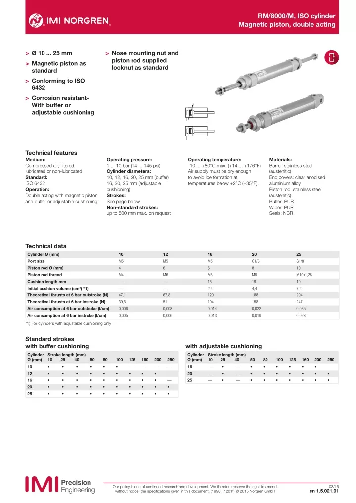
RM/8000/M, ISO cylinder Magnetic piston, double acting > Ø 10 ... 25 mm > Magnetic piston as standard > Conforming to ISO 6432 > Corrosion resistant- With buffer or adjustable cushioning > Nose mounting nut and piston rod supplied locknut as standard Technical features Medium: Compressed air, filtered, lubricated or non-lubricated Standard: ISO 6432 Operation: Double acting with magnetic piston and buffer or adjustable cushioning Operating pressure: 1 ... 10 bar (14 ... 145 psi) Cylinder diameters: 10, 12, 16, 20, 25 mm (buffer) 16, 20, 25 mm (adjustable cushioning) Strokes: See page below Non-standard strokes: up to 500 mm max. on request Operating temperature: -10 ... +80°C max. (+14 ... +176°F) Air supply must be dry enough to avoid ice formation at temperatures below +2°C (+35°F). Materials: Barrel: stainless steel (austenitic) End covers: clear anodised aluminium alloy Piston rod: stainless steel (austenitic) Buffer: PUR Wiper: PUR Seals: NBR Technical data Cylinder Ø (mm) Port size Piston rod Ø (mm) Piston rod thread Cushion length mm Initial cushion volume (cm3) *1) Theoretical thrusts at 6 bar outstroke (N) Theoretical thrusts at 6 bar instroke (N) Air consumption at 6 bar outstroke (l/cm) Air consumption at 6 bar instroke (l/cm) 10 M5 4 M4 — — 47,1 39,6 0,006 0,005 12 M5 6 M6 — — 67,8 51 0,008 0,006 16 M5 6 M6 16 2,4 120 104 0,014 0,013 20 G1/8 8 M8 19 4,4 188 158 0,022 0,019 25 G1/8 10 M10x1,25 19 7,2 294 247 0,035 0,028 *1) For cylinders with adjustable cushioning only Standard strokes with buffer cushioning with adjustable cushioning Cylinder Ø (mm) 10 12 16 20 25 Stroke length (mm) 10 25 40 • • • • • • • • • • Cylinder Ø (mm) 16 20 25 Stroke length (mm) 10 25 40 • — • — • 50 • • • • • 80 • • • • • 100 • • • • • 125 160 200 250 50 • • • 80 • • • 100 • • • 125 • • • 160 • • • 200 • • • 250 • • • • • — • • • • — • • • • — • • • • — — — — — • • — • • Our policy is one of continued research and development. We therefore reserve the right to amend, without notice, the specifications given in this document. (1998 - 1201f) © 2015 Norgren GmbH 03/16 en 1.5.021.01
RM/8000/M, ISO cylinder Magnetic piston, double acting Cylinder variants Symbol Model Non-magnetic piston Symbol Model magnetic piston Description Dimensions Page TRM/8000 *1) RM/8000/M Standard cylinder wi h integral eye mounting 4 RM/8000/MC RM/8000/MF RM/8000/MU Cylinder wi h central rear port Cylinder wi h flat rear cover Cylinder wi h extended piston rod piston rod extension 75 mm: *RM/8***/*U/stroke/75 5 5 4 RM/8000/IU TRM/8000/IU *1) RM/8000/JM Cylinder wi h double ended piston rod (Ø 16 to 25 mm) 4 RM/8017/M RM/8021/M RM/8026/M RM/8017/MU Cylinder Ø 16 mm with adjustable cushioning Cylinder Ø 20 mm with adjustable cushioning Cylinder Ø 25 mm with adjustable cushioning Cylinder Ø 16 mm with adjustable cushioning and extended piston rod 4 4 4 4 RM/8021/MU Cylinder Ø 20 mm with adjustable cushioning and extended piston rod 4 RM/8026/MU Cylinder Ø 25 mm with adjustable cushioning and extended piston rod 4 RM/8017/JM Cylinder Ø 16 mm with double ended piston rod and adjustable cushioning 4 RM/8021/JM Cylinder Ø 20 mm with double ended piston rod and adjustable cushioning 4 RM/8026/JM Cylinder Ø 25 mm with double ended piston rod and adjustable cushioning 4 RM/8000/N2 Cylinder wi h non-rotating piston rod (Ø 12 to 25 mm) 4 RM/8000/L4 Cylinder Ø 12 to 25 mm wi h locking unit (PASSIVE). achieved by spring force on removal of the signal to the unit. Operating pressure for locking unit: 4 ... 10 bar 5 *1 Cylinder (Ø 16 ... 25 mm) with heat resistant seals 150°C max. Option selector ˙RM/80˙˙/˙˙/˙˙˙ Non-standard variants High temperature version 150°C max. Cylinder Ø (mm) with buffer Substitute Stroke (mm) max. 500 Variants (non-magnetic piston) T Substitute Substitute IU Extended piston rod RM/8***/IU*/***/*** Extension (mm) Variants (magnetic piston) 10 12 16 20 25 10 12 16 20 25 Cylinder Ø (mm) with adjustable cushioning Substitute M Standard with integral eye mounting Substitute MC MF N2 JM L4 MU Central rear port Flat rear cover Non-rotating piston rod Double ended piston rod Locking unit Extended piston rod RM/8***/MU/***/*** Extension (mm) 17 21 26 16 20 25 Note: If option is not required, disregard option position within part number eg. RM/8025/M/50. For combinations of cylinder variants consult our Technical Service. Please note that heat resistant seals are not available for all variants. This options selector explains only the cylinder variants. Additional variants/options are not possible. Note: Please fill in only the numbers of digits required,e.g. RM/8025/M/50 Our policy is one of continued research and development. We therefore reserve the right to amend, without notice, the specifications given in this document. (1998 - 1201f) © 2015 Norgren GmbH en 1.5.021.02 03/16
RM/8000/M, ISO cylinder Magnetic piston, double acting Mountings 1 2 3 4 10 5 6 12 11 9 8 7 AK B, G C F FH Cyl. 4 9 5 8 1 Page 6 Page 6 1 M/P19407 M/P19408 M/P19408 M/P19409 M/P19409 L2 Page 6 Page 6 Page 6 Ø QM/8010/38 QM/8012/38 QM/8012/38 QM/8020/38 QM/8025/38 L M/P19369 M/P19389 M/P19389 M/P19406 M/P19406 N QM/8010/25 QM/8012/25 QM/8012/25 QM/8020/25 QM/8025/25 UF — QM/8012/34 QM/8012/34 QM/8020/34 QM/8020/34 Guide block with roler bearing 10 12 16 20 25 Cyl. 6 7 3 10 Page 8 2 Ø Page 6 Page 7 Page 7 Page 7 QM/947 QM/8012/24 QM/8012/24 QM/8020/24 QM/8020/24 Switch mounting brackets >15 mm stroke QM/8010/44 QM/8012/44 QM/8012/44 QM/8020/44 QM/8020/44 M/P1501/90 M/P13834 M/P13834 M/P13615 M/P13615 Magnetically operated switches QM/8010/32 QM/8012/32 QM/8012/32 QM/8020/32 QM/8025/32 — QM/8012/61/* QM/8012/61/* QM/8020/61/* QM/8025/61/* 10 12 16 20 25 Cyl. <15 mm stroke 11 Page 10 12 Page 10 Ø Page 10 & 11 QM/33/012/22 QM/33/012/22 QM/33/016/22 QM/33/020/22 QM/33/025/22 QM/33/010/23 QM/33/016/23 QM/33/016/23 QM/33/020/23 QM/33/025/23 10 12 16 20 25 * Insert standard stroke length: Ø 12 mm: 50, 100, 160, 200 and 250 mm; Ø 16 ... 25 mm: 50, 100, 160, 200, 250, 320, 400 and 500 mm., use nearest standard stroke. Our policy is one of continued research and development. We therefore reserve the right to amend, without notice, the specifications given in this document. (1998 - 1201f) © 2015 Norgren GmbH en 1.5.021.03 03/16
RM/8000/M, ISO cylinder Magnetic piston, double acting Basic dimensions RM/8000/M Dimensions in mm Projection/First angle XC + # WF G G PL BF PL EE EW- 0,1 L AM L 12 MR VD EE CD H9 D ø BA - 0,1 ø MM h9 ø B - 0,1 KK BE BE 1 2 4 KV VA LB KW 1 # Stroke KW KV Ø AM Ø B/BA -0,1 BE BF Ø CD H9 Ø D EE EW -0,1 G KK KW KW1 L Model 10 12 16 20 25 Ø 12 16 16 20 22 L12 12 16 16 22 22 LB M12x1,25 M16x1,5 M16x1,5 M22x1,5 M22x1,5 Ø MMh9 12 17 17 20 22 MR 4 6 6 8 8 PL 16,5 21 21 30 30 M5 M5 M5 G1/8 G1/8 7,9 11,9 11,9 15,9 15,9 9 9,5 9,5 15 15 WF M4 M6 M6 M8 M10x1,25 VA/VD 19 22 22 27 27 XC 6 5 5 8 8 at 0 mm 2 3 3 4 5 per 25 mm 6 9 9 12 12 RM/8010/M/* RM/8012/M/* RM/8016/M/* RM/8020/M/* RM/8025/M/* Model 1 2 4 10 12 16 20 25 – 3 3 3 4 2 3 4 3 7 4 6 6 8 10 8 8 7 11 9 5,5 5,5 5,5 8 8 7 10 10 13 17 – 5 5 7 9 14 19 19 27 27 16 22 22 24 28 1,5 2 2 2 2 64 75 82 95 104 0,034 kg 0,058 kg 0,070 kg 0,145 kg 0,200 kg 0,007 kg 0,011 kg 0,012 kg 0,018 kg 0,028 kg RM/8010/M/* RM/8012/M/* RM/8016/M/* RM/8020/M/* RM/8025/M/* * Please insert standard stroke length. Alternative variants RM/8017/M, RM/8021/M, RM/8026/M – Cylinder with adjustable cushioning 1 1 Ø 16 20 25 at 0 mm 0,070 kg 0,145 kg 0,195 kg per 25 mm 0,012 kg 0,018 kg 0,028 kg Model RM/8017/M/* RM/8021/M/* RM/8026/M/* * Please insert standard stroke length. 1 Cushion screw RM/8000/N2 – Cylinder with non-rotating piston rod A - B A Ø Torque max. at 0 mm per 25 mm Model 1 12 16 20 25 5 5 6 8 0,04 Nm 0,04 Nm 0,15 Nm 0,25 Nm 0,058 kg 0,070 kg 0,145 kg 0,200 kg 0,011 kg 0,012 kg 0,018 kg 0,028 kg RM/8012/N2/* RM/8016/N2/* RM/8020/N2/* RM/8025/N2/* B 1 * Please insert standard stroke length. RM/8000/JM – Cylinder with double ended piston rod ZM + 2 x # L 8 + # Ø L8 ZM at 0 mm per 25 mm Model 16 20 25 56 68 69 100 116 125 0,080 kg 0,165kg 0,250 kg 0,017 kg 0,028 kg 0,043 kg RM/8016/JM/* RM/8020/JM/* RM/8025/JM/* * Please insert standard stroke length. # Stroke Our policy is one of continued research and development. We therefore reserve the right to amend, without notice, the specifications given in this document. (1998 - 1201f) © 2015 Norgren GmbH en 1.5.021.04 03/16
RM/8000/M, ISO cylinder Magnetic piston, double acting Alternative variants RM/8000/MC – Cylinder with central rear port Dimensions in mm Projection/First angle RM/8000/MF – Cylinder with flat rear cover ZJ + # ZJ + # EE EE EE EE # Stroke Ø 10 12 16 20 25 EE M5 M5 M5 G1/8 G1/8 ZJ 62 72 78 92 97 at 0 mm 0,031 kg 0,052 kg 0,064 kg 0,130 kg 0,185 kg per 25 mm 0,007 kg 0,011 kg 0,012 kg 0,018 kg 0,028 kg Model RM/8010/M/* RM/8012/M/* RM/8016/M/* RM/8020/M/* RM/8025/M/* * Please insert standard stroke length. RM/8000/L4 – Cylinder with locking unit XC + # AB ø AF EE AL BE AH BE AK AC AG BF WF AD # Stroke Ø 12 16 20 25 Ø 12 16 20 25 AB 21 21 24 24 BE M16 x 1,5 M16 x 1,5 M22 x 1,5 M22 x 1,5 AC 13 13 14 14 BF 12 12 23 23 AD 48,5 48,5 66 65 EE M5 M5 M5 M5 Ø AF 20 20 22 22 WF 18,5 18,5 31 30 AG 20 20 27 27 XC 109 116 145 151,5 AH 20 20 33 33 Locking forces 200 N 200 N 350 N 400 N AL 43,5 43,5 45,5 45,5 at 0 mm 0,130 kg 0,140 kg 0,300 kg 0,360 kg AK 10 10 16,5 16,5 per 25 mm 0,011 kg 0,012 kg 0,018 kg 0,028 kg Model RM/8012/L4/* RM/8016/L4/* RM/8020/L4/* RM/8025/L4/* Model RM/8012/L4/* RM/8016/L4/* RM/8020/L4/* RM/8025/L4/* * Please insert standard stroke length. Our policy is one of continued research and development. We therefore reserve the right to amend, without notice, the specifications given in this document. (1998 - 1201f) © 2015 Norgren GmbH en 1.5.021.05 03/16
RM/8000/M, ISO cylinder Magnetic piston, double acting Mountings Piston rod swivel AK Conforms to DIN ISO 8139 Dimensions in mm Projection/First angle Projection/First angle Dimensions in mm Front or rear flange G and B UR FB MF 3 2 4 1 4° KK KK UF 4° TF B 1 F L 2 L Ø KK B1 F L L2 kg Model (AK) Ø 10 12/16 20/25 Ø FB 4,5 5,5 6,6 MF 3 4 5 TF 30 40 50 UF 40 51 63 UR 22 28 38 kg 0,02 0,03 0,05 Model (B, G) M/P19407 M/P19408 M/P19409 1 2 3 4 10 12/16 M 6 20 25 M 4 2 3 4 5 12,5 33 14 18 26 8 12 16 20 11 7 10 19 3,2 7 5 7 12 11 13 17 30 0,01 QM/8010/38 0,02 QM/8012/38 0,05 QM/8020/38 0,2 QM/8025/38 39 55 73 10 13 17 M 8 M 10 x 1,25 Piston rod clevis F Conforms to DIN ISO 8140 Foot C Conforms to DIN ISO 6432 RK CL CM CE ø CK h11 LE AT AH KK CL ER AU AO ø AB TR E Ø 10 12/16 M6 20 25 KK M4 CE 16 24 32 Ø CK h11 CL 4 6 8 10 CM 4 6 8 10 ER 6,5 9,5 13 16 LE 8 12 16 20 RK 11,5 0,01 QM/8010/25 17,5 0,02 QM/8012/25 22 0,06 28 0,10 kg Model (F) Ø 10 12/16 20/25 Ø AB 4,5 5,5 6,6 AH 16 20 25 AO 6 6 7,5 AT 2 3 4 AU 10 13 16 E 35 43 53 TR 25 32 40 kg 0,02 0,03 0,06 Model (C) M/P19369 M/P19389 M/P19406 8 12 16 20 M8 M10 x1,25 40 QM/8020/25 QM/8025/25 Rear hinge L Front or rear detachable trunnion FH K 1 G 1 K 3 TL TM ø TD +0,03 UW CA H 2 ø S G 2 G 3 G 4 L1 K 2 Ø 12/16 20/25 L1 8 8 Ø TD +0,03 6 6 TL 10 10 TM 38 46 UW 25 30 kg 0,05 0,07 Model (FH) QM/8012/34 QM/8020/34 Ø 10 12/16 20/25 CA G1 12 20 25 G2 – 15 15 G3 15 30 35 G4 6 8 10 H2 1 1,5 2 K1 13,5 20 25 K2 10,5 15 20,5 K3 2 3 3 Ø S 4,8 5,5 6,6 kg 0,01 0,02 0,04 Model (L) QM/947 QM/8012/24 QM/8020/24 6,5 18,5 20 Our policy is one of continued research and development. We therefore reserve the right to amend, without notice, the specifications given in this document. (1998 - 1201f) © 2015 Norgren GmbH en 1.5.021.06 03/16
RM/8000/M, ISO cylinder Magnetic piston, double acting Nose nut N Rear hinge L2 Dimensions in mm Projection/First angle K 1 G 1 CA H 2 KW BE ø S G 2 G 3 G 4 K 2 Ø CA G1 G2 G3 G4 H2 K1 K2 Ø S kg Model (L2) Ø BE KW kg Model (N) 10 12/16 20/25 24 27 30 11 13 16 12,5 20 15 20 4 5 6 2,5 3 4 17,5 13 23 29,5 24 4,5 5,5 6,6 0,018 QM/8010/44 0,035 QM/8012/44 0,077 QM/8020/44 10 12/16 20/25 M12x1,25 M16x1,5 M22x1,5 19 22 27 6 5 8 0,01 0,01 0,02 M/P1501/90 M/P13834 M/P13615 25 32 18 Universal piston rod eye UF Conforms to DIN ISO 8139 CE EN h12 CN H 7 Z Z KK EP ER LE AX Ø 10 12/16 M6 20 25 KK M4 AX CE Ø CN H7 14 27 14 30 16 36 42 EN -0,1 8 9 12 14 ER LE 8 9 11 14 Z 5˚ 5˚ 5˚ 5˚ kg 0,02 QM/8010/32 0,02 QM/8012/32 0,05 QM/8020/32 0,08 QM/8025/32 Model (UF) 5 6 8 10 10 11 13 15 M8 M10 x 1,25 25 Our policy is one of continued research and development. We therefore reserve the right to amend, without notice, the specifications given in this document. (1998 - 1201f) © 2015 Norgren GmbH en 1.5.021.07 03/16
RM/8000/M, ISO cylinder Magnetic piston, double acting QM/8000/61 – Guide block EA + # FC EB EW 2,5 + EC FL -0,1 ø FS FM EZ Dimensions in mm Projection/First angle EP EO EM EK EM EL FW FH FK ER FJ -0,1 FV 2,5 + FP 1 EG ø FR f6 FO H7 ED 2,5 2 EJ EF ES EC 2 ET -0,1 # Stroke 1 Centering sleeve 2 Adjustable 3 Safety zone EV 2,5 + ø FO ø EY ø EX FG H7 FB FE FA EZ ø FD ø FF 3 Ø 12/16 132 20 25 Ø EA EB 75 108 108 FB EC 32,5 32,5 32,5 FC ED 16,5 19 19 Ø FD FE EF 37 58 58 EG 10 12 12 FF EJ 76 90 90 Ø FG H7 EK 63 76 76 FH EL 46 58 58 FJ EM 24 38 38 FK EO 10 13 17 FL EP 8 13 13 FM ER 24 38 38 Ø FO H7 ES 65 75 75 FP ET 6,5 8,5 8,5 Ø FR f6 EV 4,6 5,7 5,7 ØFS EW 27 32 32 FV Ø EX Ø EY 8 10 10 FW EZ M4 M5 M5 kg per 100 mm Model QM/8012/61 QM/8020/61 QM/8025/61 Model 4,5 5,5 5,5 kg at 0 mm 160 160 FA 12/16 6 20 25 22 23 23 30 34 34 5,5 6,6 6,6 M 4 9 M 6 M 6 6 9 9 32 40 40 54 68 68 65 79 79 15 20 20 10 14 14 9 9 9 M5 M 6 M 6 6 9 9 8 10 10 M 6 M 8 M 10 x 1,25 37 27 37 0,40 0,65 0,65 0,04 0,06 0,06 QM/8012/61 QM/8020/61 QM/8025/61 7 7 11 11 Note: supplied complete with cylinder mounting screws and two centering sleeves Our policy is one of continued research and development. We therefore reserve the right to amend, without notice, the specifications given in this document. (1998 - 1201f) © 2015 Norgren GmbH en 1.5.021.08 03/16
RM/8000/M, ISO cylinder Magnetic piston, double acting Maximum load for QM/8000/61 Dimensions in mm Projection/First angle 1 1 f 2 2 1 Centre of gravity load capacity 2 Outstroke Maximum load capacity is dependent on the outstroke of a horizontally installed guide unit. In the case of short stroke operation, the load capacity figures taken from the diagram must be multiplied by the correction factor (diagram 2). In the curves of load capacity (diagram 1), the short stroke corrections have already been taken into account for an outstroke > 60 mm. The total deflection of guide rods will be determined by the addition of that due to own weight (diagram 3) and that due to load capacity (diagram 4). Maximum load capacity depending on outroke (diagram 1) Deflection caused by own weight (diagram 3) Deflection caused by a load of 10 N (diagram 4) (diagram 2) Load capacity Correction factor Deflection (mm) Deflection (mm) f f ø 20 & 25 2,5 1,0 2,5 100 2,0 ø 20 & 25 2,0 0,9 80 1,5 1,5 0,8 60 1,0 1,0 0,7 40 ø 12 & 16 ø 20 & 25 ø 12 & 16 0,5 0,5 0,6 20 ø 12 & 16 0 0,5 0 0 20 40 60 0 0 100 200 300 400 500 600 0 100 200 300 400 500 600 0 100 200 Outstroke (mm) 300 400 500 600 Stroke (mm) Reduction of load capacity for short stroke operation Outstroke (mm) Outstroke (mm) Stroke (mm) Our policy is one of continued research and development. We therefore reserve the right to amend, without notice, the specifications given in this document. (1998 - 1201f) © 2015 Norgren GmbH en 1.5.021.09 03/16
RM/8000/M, ISO cylinder Magnetic piston, double acting Technical data - Reed switches - additional informations see data sheet N/en 4.3.005 Symbol Voltage Current maximum (mA) Function Operating temperature (°C) -25 ... +80 -25 ... +80 LED Protection class Plug Cable length (m) 2, 5 or 10 5 Cable type Weight Model (V a.c.) (V d.c.) 10 ... 240 10 ... 170 180 10 ... 240 10 ... 170 180 (g) 37 37 Closer Closer • • IP66 IP66 — — PVC 2 x 0,25 PUR 2 x 0,25 M/50/LSU/*V M/50/LSU/5U ~+ BN BU ~ 10 ... 240 10 ... 170 180 Closer -25 ... +150 — IP66 — 2 Silicon 2 x 0,25 37 TM/50/RAU/2S BN BU 10 ... 240 10 ... 170 180 Changeover -25 ... +80 — IP66 — 5 PVC 3 x 0,25 37 M/50/RAC/5V BK BU BN 10 ... 60 10 ... 60 180 Closer -25 ... +80 • IP66 M8 x 1 0,3 PVC 3 x 0,25 16 M/50/LSU/CP *1) 1 + ~ BN 4 BK ~ * Insert cable length; *1) Plug-in connector see page 11; Color code: BK = black, BN = brown, BU = blue Drawings A-B Dimensions in mm Projection/First angle M/50/LSU/*V, M/50/LSU/5U, TM/50/RAU/2S Cable length L = 2, 5 or 10 m +30 L 50+10 30 5,1 1 A ø 6,4 1,5 B 2 A-B +30 50+10 L M/50/RAC/5V Cable length L = 5 m 30 1 5,1 A ø 6,4 1,5 B 3 M/50/LSU/CP X A-B 300±15 30 31,5 ... 36 5,1 1 4 BK A ø 6,4 X 1 BN 3 BU 1,5 B 4 1 Fixing screw 2 + BN = brown; - BU = blue (output) 3 - BK = black; + BN = brown; - ≠BU = blue 4 Plug M8 x 1, color code: BK = black; BN = brown; BU = blue Switch mounting brackets - Brackets > 15 mm stroke Switch mounting brackets - Brackets < 15 mm stroke 1 B 10 1 S T R max. 2 2 1 Magnetically operated switch 2 Switch mounting bracket 1 Magnetically operated switch 2 Switch mounting bracket Ø 10 12 16 20 25 B 8 8 10 10 10 R max. 16 18 20 22 24 kg 0,01 0,01 0,01 0,01 0,01 Model QM/33/010/22 QM/33/012/22 QM/33/016/22 QM/33/020/22 QM/33/025/22 Ø 10 12 16 20 25 S 27,5 28,5 29,5 29,5 31,5 T 19,5 21,5 23,5 26 28,5 kg 0,01 0,01 0,01 0,01 0,01 Model QM/33/010/23 QM/33/016/23 QM/33/016/23 QM/33/020/23 QM/33/025/23 Our policy is one of continued research and development. We therefore reserve the right to amend, without notice, the specifications given in this document. (1998 - 1201f) © 2015 Norgren GmbH en 1.5.021.10 03/16
RM/8000/M, ISO cylinder Magnetic piston, double acting Technical data - Solid state - additional informations see data sheet N/en 4.3.007 Symbol Voltage Current maximum (mA) 150 150 Function Operating temperature (°C) -40 ... +80 -40 ... +80 LED Protection class Plug Cable length Cable type Weight Model (V d.c.) 10 ... 30 10 ... 30 (m) 2, 5 or 10 5 (g) 37 37 PNP PNP • • IP67 IP68 — — PVC 3 x 0,12 PUR 3 x 0,14 M/50/EAP/*V M/50/EAP/5U + BN BU BK A pnp 10 ... 30 10 ... 30 150 150 PNP PNP -40 ... +80 -40 ... +80 • • IP67 IP67 M8 x 1 M12 x 1 0,3 0,3 PVC 3 x 0,14 PVC 3 x 0,14 16 16 M/50/EAP/CP *1) M/50/EAP/CC *1) 1 3 + BN BU BK A pnp 4 10 ... 30 150 NPN -40 ... +80 • IP67 — 2, 5 or 10 PVC 3 x 0,12 37 M/50/EAN/*V BU BN BK + A npn 10 ... 30 150 Closer -40 ... +80 • IP67 M8 x 1 0,3 PVC 3 x 0,14 16 M/50/EAN/CP *1) 3 1 + BU BN BK A npn 4 * Insert cable length; *1) Plug-in connector below; Color code: BK = black, BN = brown, BU = blue Drawings M/50/EAP/*V, M/50/EAN/*V Cable length L = 2, 5 or 10 m 5,1 Dimensions in mm Projection/First angle A-B +30 42±4 L 30 1 A ø 6,4 1,5 B 2 X A-B 300±15 M/50/EAP/CP, M/50/EAN/CP 30 31,5 ... 36 5,1 1 4 BK A ø 6,4 X 1 BN 3 BU 1,5 B 3 M/50/EAP/CC X A-B 300±15 30 47,5 1 5,1 3 BU 4 BK A ø 6,4 X 1 BN 1,5 4 1 Fixing screw 2 Color code: BK = black; BN = brown; BU = blue 3 Plug M8 x 1 4 Plug M12 x 1 Accessories Plug-in connector cable with nut Outer cover PVC 3 x 0,25 PUR 3 x 0,25 PUR 3 x 0,34 Warning These products are intended for use in industrial compressed air systems only. Do not use these products where pressures and temperatures can exceed those listed under »Technical features/data«. Before using these products with fluids other than those specified, for non-industrial applications, life-support systems or other applications not within published specifications, consult IMI Precision Engineering, Norgren GmbH Through misuse, age, or malfunction, components used in fluid power systems can fail in various modes. Cable length (m) 5 m 5 m 5 m Weight (kg) 0,18 0,18 0,21 Connector M8 x 1 M8 x 1 M12 x 1 Connector M/P73001/5 M/P73002/5 M/P34594/5 EN The system designer is warned to consider the failure modes of all component parts used in fluid power systems and to provide adequate safeguards to prevent personal injury or damage to equipment in the event of such failure. System designers must provide a warning to end users in the system instructional manual if protection against a failure mode cannot be adequately provided. System designers and end users are cautioned to review specific warnings found in instruction sheets packed and shipped with these products. Our policy is one of continued research and development. We therefore reserve the right to amend, without notice, the specifications given in this document. (1998 - 1201f) © 2015 Norgren GmbH en 1.5.021.11 03/16 DE Diese Produkte sind ausschließlich in Druckluftsystemen zu verwenden. Sie sind dort einzusetzen, wo die unter »Technische Merkmale/-Daten« aufgeführten Werte nicht überschritten werden. Berücksichtigen Sie bitte die entsprechende Katalogseite. Vor dem Einsatz der Produkte bei nicht industriellen Anwendungen, in lebenser- haltenden- oder anderen Systemen, die nicht in den veröffentlichten Anleitungsunterlagen enthalten sind, wenden Sie sich bitte direkt an IMI Precision Engineering, Norgren GmbH Durch Missbrauch, Verschleiß oder Störungen können in Pneumatik- systemen verwendete Komponenten auf verschiedene Arten versagen. Systemauslegern wird dringend empfohlen, die Störungsarten aller in Pneumatiksystemen verwendeten Komponententeile zu berück- sichtigen und ausreichende Sicherheitsvorkehrungen zu treffen, um Verletzungen von Personen sowie Beschädigungen der Geräte im Falle einer solchen Störung zu verhindern. Systemausleger sind verpflichtet, Sicherheitshinweise für den End- benutzer im Betriebshandbuch zu vermerken, wenn der Störungs- schutz nicht ausreichend gewährleistet ist. PL Te produkty są przeznaczone do pracy wyłącznie w przemysłowych układach ze sprężonym powietrzem i płynami. Nie używać produktów tam, gdzie ciśnienia i temperatury mogą przekroczyć parametry podane w sekcji „Cechy/Dane techniczne”. Przed użyciem produktów z płynami innymi niż określono i w celach innych niż przemysłowe, w systemach podtrzymywania życia i w innych zastosowaniach niewymienionych w opublikowanych specyfikacjach należy skontaktować się z IMI Precision Engineering, Norgren GmbH W wyniku niewłaściwego użytkowania lub procesów zużycia oraz usterek, zastosowane komponenty w pneumatycznych i hydraulicznych układach zasilających mogą ulec awarii. Przestrzega się konstruktorów do zastosowania wszelkich środków bezpieczeństwa w celu uniknięcia obrażeń osobistych i zniszczenia mienia na wypadek awarii komponentów zastosowanych w układzie zasilania. Przestrzega się konstruktorów układów, aby zapoznać się ze szczególnymi ostrzeżeniami zamieszczonymi na kartach danych z instrukcjami, które są pakowane i wysyłane razem z produktami. FR Les produits de ce catalogue ne conviennent que pour les systèmes industriels fonctionnant à l‘air comprimé. Ne jamais soumettre ces appareils à des pressions ou à des températures autres que celles indiquées dans les caractéristiques techniques. Pour une utilisation avec un fluide non spécifié dans cette fiche technique, les applications non industrielles, les appareils de respiration artificielle ou toute autre application ne correspondant pas à nos spécifications, consultez notre service technique IMI Precision Engineering, Norgren GmbH Une utilisation abusive, l’âge des appareils ou leur manque d’entretien peuvent entraîner différents types de dysfonctionnements. Il est conseillé aux concepteurs de machines d’étudier tous les modes de défaillance de chacun des composants et de prévoir les protections nécessaires de manière à éviter tout accident corporel ou tout dommage aux systèmes environnants en cas de défaillance de l’un de ceux-ci. Lorsqu‘une protection appropriée ne peut être installée, le concepteur de machine devra informer les utilisateurs des risques encourus par une mention portée dans sa notice d’utilisation. Il est recommandé aux concepteurs de systèmes et aux utilisateurs de prendre connaissance des mises en garde portées sur les feuillets fournis avec les appareils ou bien indiquées directement sur ces derniers. ES Estos productos están destinados a que se utilicen únicamente en sistemas industriales de aire comprimido. No utilizar estos productos cuando la presión y temperatura puedan exceder las especificadas en los ‘Datos Técnicos ’. Antes de utilizar estos productos con fluidos que no sean los especificados, para aplicaciones no industriales, sistemas médicosanitarios u otras aplicaciones que no se encuentren entre las especificaciones publicadas, consultar IMI Precision Engineering, Norgren GmbH Por mal uso, antigüedad o montaje deficiente, los componentes utilizados en sistemas de fluidos energéticos pueden fallar y provocar diversos tipos de accidentes. Se advierte a los diseñadores de sistemas que deben considerar la posibilidad de mal funcionamiento de todos los componentes utilizados en sistemas de fluidos y prever las medidas adecuadas de seguridad para evitar daños personales o desperfectos en el equipo en el supuesto de producirse tales fallos. En el caso de no poder proporcionar la protección adecuada frente a algún fallo, los diseñadores del sistema deben advertirlo al usuario final en el manual de instrucciones. Se aconseja a los diseñadores del sistema, así como a los usuarios finales, que revisen las advertencias especificadas de montaje que se indican en las hojas técnicas. IT Questi prodotti sono adatti solo per l’impiego in impianti industriali funzionanti con aria compressa. Non devono essere utilizzati nei casi in cui le condizioni di pressione e di temperatura non rientrino nei valori indicati nelle ‘Caratteristiche Tecniche’. Prima di utilizzare questi prodotti con fluidi differenti da quelli indicati, per applicazioni non industriali, sistemi medico-sanitari o altre applicazioni non specificatamente indicate nella documentazione, consultare la IMI Precision Engineering, Norgren GmbH In seguito all’utilizzo errato, l’invecchiamento o al mal funzionamento, i componenti utilizzati in impianti pneumatici possono danneggiarsi. I progettisti degli impianti devono prendere in considerazione tutte le possibilità di rottura dei componenti utilizzati nell’impianto pneumatico e prevedere dispositivi di sicurezza per evitare lesioni all’operatore o danneggiamenti all’impianto. Se le protezioni non sono adeguatamente sicure, il progettista deve informare l’utilizzatore finale nel Manuale di Istruzione. Si consiglia agli utilizzatori ed ai progettisti di prendere in considerazione