Download
1 / 20
200 likes | 210 Views
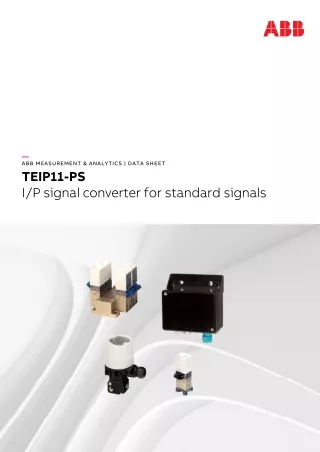
"The TEIP11-PStherefore a connecting link between electrical/electronic and pneumatic systems. The signal conversion process is similar to the patented force balance method. Special features of the TEIP11-PS signal converter are its relatively small dimensions and outstanding operational stability when subject to shock and vibration. The converter can be subjected to loads up to 10 g with less than 1% effect on function.<br><br>The housing units are available in a variety of models to meet your installation requirements. For potentially explosive conditions, units that offer intrinsically safe operation or pressure-resistant encapsulation are available with international approval certificates for use worldwide."<br>For More Information visit on our website:- www.instronline.com<br>Our E-mail Address:-info@instronline.com <br>

E N D
— ABB MEASUREMENT & ANALYTICS | DATA SHEET TEIP11-PS I/P signal converter for standard signals — ABB Limited Measurement & Analytics Howard Road, St. Neots Cambridgeshire, PE19 8EU UK Tel: +44 (0)870 600 6122 Fax: +44 (0)1480 213 339 Email: enquiries.mp.uk@gb.abb.com ABB Inc. Measurement & Analytics 125 E. County Line Road Warminster, PA 18974 USA Tel: +1 215 674 6000 Fax: +1 215 674 7183 ABB Automation Products GmbH Measurement & Analytics Schillerstr. 72 32425 Minden Germany Tel: +49 571 830-0 Fax: +49 571 830-1806 abb.com/positioners DS/TEIP11-PS-EN Rev. E 08.2018 — We reserve the right to make technical changes or modify the contents of this document without prior notice. With regard to purchase orders, the agreed particulars shall prevail. ABB does not accept any responsibility whatsoever for potential errors or possible lack of information in this document. We reserve all rights in this document and in the subject matter and illustrations contained therein. Any reproduction, disclosure to third parties or utilization of its contents – in whole or in parts – is forbidden without prior written consent of ABB. Copyright© 2018 ABB All rights reserved 3KXE311001R1001
2 TEIP11-PS I/P SIGNAL CONVERTER FOR STANDARD SIGNALS | DS/TEIP11-PS-EN REV. E TEIP11-PS I/P SIGNAL CONVERTER FOR STANDARD SIGNALS | DS/TEIP11-PS-EN REV. E 19 — Proven and reliable concept — Integral mount design • Small dimensions, low weight — Sturdy construction and solid functionality • Influence of shock and vibration < 1 % at 10 g — Variety of signal ranges • Input e.g. 0 to 20 mA or 4 to 20 mA • Output 0.2 to 1 bar (3 to 15 psi) — Complies with the following directives • EMC directive 2014/30/EU • EC directive for CE declaration of conformity — Wide temperature range • From –40° (optional –55°) to 85 °C (–40° [optional –67°] to 185 °F
TEIP11-PS I/P SIGNAL CONVERTER FOR STANDARD SIGNALS | DS/TEIP11-PS-EN REV. E 3 Change from one to two columns — Concept The TEIP11-PS signal converter converts standard electrical signals, e.g. 4 to 20 mA to 0.2 to 1 bar (3 to 15 psi). It is therefore a connecting link between electrical/electronic and pneumatic systems. The signal conversion process is similar to the patented force balance method. Special features of the TEIP11-PS signal converter are its relatively small dimensions and outstanding operational stability when subject to shock and vibration. The converter can be subjected to loads up to 10 g with less than 1% effect on function. The housing units are available in a variety of models to meet your installation requirements. For potentially explosive conditions, units that offer intrinsically safe operation or pressure-resistant encapsulation are available with international approval certificates for use worldwide. Various ranges can be supplied on the input side and the output side for signal conversion (see Specification on page 4). The device requires only compressed air 1.4 bar (20 psi) for the power supply. — Designs 1 Control room housing for rail mounting 2 Control room housing unit for block mounting 3 Plastic field mount housing 4 Aluminum or stainless steel field mount housing Figure 1: TEIP11-PS designs Control room housing unit for rail mounting The control room housing for rail mounting is the simplest and lowest priced version of the I/P signal converter. A mounting base that is compatible with all commercially available EN rails is used for installation. The housing unit with plastic cap has an IP 20 protection rating. Control room housing unit for block mounting The control room housing unit for block mounting enables you to install a number of converters in a small space. This design features central air supply via connection block and stop valves in the air connectors of the integrated signal converter. A maximum of 4 signal converters can be fitted on the connection blocks required for block mounting. If necessary, 2 or 3 (or max. 4) connection blocks can be connected to each other to create block units of 4-8-12-16 signal converters. Stop valves allow you to mount or remove individual converters during operation.
4 TEIP11-PS I/P SIGNAL CONVERTER FOR STANDARD SIGNALS | DS/TEIP11-PS-EN REV. E — … Designs — Specification Field mount housing Input (electric) The field mount housing is suited for installation on-site or in open areas. The housing can be made from plastic with IP rating IP 54, from aluminum with IP rating IP 65 and from stainless steel with IP rating IP 65. The housing is suited for wall mounting and for 2 in pipe mounting. A specially designed signal converter in a plastic housing unit enables the use of combustible gas as a power supply instead of the standard compressed air. Signal range 0 to 20 mA or 4 to 20 mA 0 to 10 mA or 10 to 20 mA 4 to 12 mA or 12 to 20 mA (additional ranges available upon request) Input resistance Ri = 260 Ω at 20 °C (68 °F), Tk + 0.4 %/K Overpressure limit 30 mA (for Ex devices see Ex relevant specifications on page 8). Capacitance / inductance Negligible Output (pneumatic) Signal range 0.2 to 1 bar (3 to 15 psi) Air capacity ≥ 5 kg/h = 4.1 Nm3/h = 2.4 scfm Load power in accordance with VDE / VDI 3520 ≥ 0.95 kg/h = 0.9 Nm3/h = 0.5 scfm Power supply (pneumatic) Instrument air Free of oil, water, and dust acc. to DIN/ISO 8573-1 Pollution and oil content according to Class 3 Pressure dew point 10 K below operating temperature Supply pressure 1.4 bar (20 psi) 2.5 bar (36 psi)* Output signal 0.2 to 1 bar (3 to 15 psi) 0.4 to 2 bar (6 to 30 psi)* * Valid for Option 509 only – increased input signal. Air consumption ≤ 0.2 kg/h = 0.16 Nm3/h = 0.1 scfm
TEIP11-PS I/P SIGNAL CONVERTER FOR STANDARD SIGNALS | DS/TEIP11-PS-EN REV. E 5 Transmission data and contributing factors Operating conditions at installation site Characteristic curve Linear, direct, or reverse action Characteristic curve deviation ≤ 0.5 % Hysteresis ≤ 0.3 % Dead band ≤ 0.1 % Temperature ≤ 1 % / 10 K within –20 to 85 °C (–4 to 185 °F) ≤ 2 % / 10 K within –55 to –20 °C (–67 to –4 °F) Power supply ≤ 0.3 % / 0.1 bar (1.5 psi) change in pressure Mechanical vibration ≤ 1 % to 10 g and 20 to 80 Hz Seismic vibration Meets the requirements of DIN IEC 68-3-3 Class III for strong and strongest earthquakes. Mounting orientation Zero point≤ 0.4 % at 90° change of position Step response 10 to 90 % and 90 to 10 % 0.6 s 5 to 15 % and 15 to 5 % 0.25 s 45 to 55 % and 55 to 45 % 0.2 s 85 to 95 % and 95 to 85 % 0.15 s EMC Meets the requirements of EMC Directive 2014/30/EU (increased interference immunity as per EN 50082-2 PR) CE Marking Complies with the EC directive for CE conformity Ambient temperature Depending on the ordered model: −40 to 85 °C (−40 to 185 °F) –55 to 85 °C (–67 to 185 °F) For Ex d: −40 to 85 °C (−40 to 185 °F) Mounting position Any Environmental capabilities Climate class GPF or FPF acc. to DIN 40040 Temperature: –55 to 85 °C (–67 to 185 °F), –45 to 85 °C (–49 to 185 °F) Relative humidity for operation, storage, or transport: 75 % average, 95 % short-term, no condensation
6 TEIP11-PS I/P SIGNAL CONVERTER FOR STANDARD SIGNALS | DS/TEIP11-PS-EN REV. E — … Specification Design for field mount housing (plastic) Design for rail mounting Material / IP rating Polyester housing unit, black, IP 54 Mounting Wall or 2 in pipe mounting (2 in pipe mounting for vertical pipes only) Electrical connection 2-pole screw terminal for 2.5 mm2 (14 AWG) in housing PG 11 cable gland for cable entry Pneumatic connection ⅛ NPT-threaded hole for supply air and output Air outlet For gas exhaust with 6 mm (0.24 in) cut or crimp connection Mounting position Any Weight 1.0 kg (2.20 lb) Dimensions Refer to Dimensions on page 10. Material / IP rating IP 20 aluminum housing unit, with plastic cover Mounting Rail mounting: EN 50022 - 35 × 7.5 EN 50035 - G 32 EN 50045 - 15 × 5 Electrical connection 2-pole screw terminal for 2.5 mm2 (14 AWG) Pneumatic connection ⅛ NPT threaded hole for supply air and output Weight 0.25 kg (0.55 lb) Dimensions Refer to Dimensions on page 10. Design for block mounting Material / IP rating IP 20 aluminum housing unit, with plastic cover Mounting In block format with special connection block (accessory), max. 4 connection blocks each with 4 signal converters Electrical connection 2-pole screw terminal for 2.5 mm2 (14 AWG) Pneumatic connection ⅜ NPT threaded hole for supply air (main connection to connection block) ⅛ NPT threaded hole for output (on each individual signal converter) Mounting position Any Weight 0.3 kg (0.66 lb) Dimensions Refer to ‘Dimensions’.
TEIP11-PS I/P SIGNAL CONVERTER FOR STANDARD SIGNALS | DS/TEIP11-PS-EN REV. E 7 Design for field housing unit (aluminum/stainless steel) Accessories ‘Ex d’ cable gland Brass, with M20 × 1.5 thread Stainless steel mounting bracket for wall mounting or 2 in pipe mounting For aluminum or stainless steel field housing unit Material for block mounting Connection block for 4 signal converters, End panel with central supply air connection ⅜ NPT, dummy panel Material / IP rating IP 65 aluminum or stainless steel housing unit Surface Aluminum housing, painted with dual component coating, lower section, black, RAL 9005, screw-on cover, Pantone 420, stainless steel housing unit, electrolytically polished Mounting Wall or 2 in pipe mounting With stainless steel mounting bracket (accessory) Electrical connection 2-pole screw terminal for 2.5 mm2 (14 AWG) in the housing, screw connection NPT ½ in for the cable entry. For ATEX ‘intrinsically safe’: Threaded hole NPT ½ in for the cable entry For ATEX ‘Ex d’: M20 × 1.5 threaded hole for cable entry at FM/CSA (Cable gland with Ex d approval available as an accessory on request) Pneumatic connection ¼ in NPT threaded hole for supply air and output Weight 0.62 kg (1.37 lb) with aluminum housing unit 1.20 kg (2.65 lb) for stainless steel housings. Dimensions Refer to Dimensions on page 10.
8 TEIP11-PS I/P SIGNAL CONVERTER FOR STANDARD SIGNALS | DS/TEIP11-PS-EN REV. E Operation as intrinsically safe equipment — Ex relevant specifications Flameproof (enclosure), ATEX ‘Ex d’ Marking II 2G Ex d IIC T4/T5/T6 Gb Type Examination Test Certificate DMT 02 ATEX E 121 X Marking II 2G Ex ia IIC T6 resp. T4 Gb Type DOC. 900771 Type Examination Test Certificate TÜV 99 ATEX 1487 X Device class II 2G Type TEIP11, Standards EN 60079-0: 2012 Doc. 901068-SMDxxxx (General requirements) TEIP11-PS, EN 60079-1: 2007 Doc. 901068-SMDxxxx (Flameproof enclosure ‘d’) TEIP11-PS, Doc. 901069-SMDxxxx System bus, computer interfaces Device class II 2G Current ≤ 50 mA Standards EN 60079-0:2009 EN 60079-11:2012 Temperature classes for the following versions: TEIP11 Doc. 901068-SMD and TEIP11-PS Doc. 901068-SMD and TEIP11-PS Doc. 901069-SMD Pneumatic data Supply pressure 1.4 bar (20 psi) / 2.5 bar (37 psi)* Output signal 0.2 to 1 bar (3 to 15 psi) / 0.4 to 2 bar (6 to 30 psi)* Temperature class Input current Ambient temperature range * Valid for Option 509 only – increased input signal. T4 120 mA –55 to 60 °C T4 100 mA –55 to 85 °C Thermal data T4: –40 °C < Tamb < 85 °C T6 TEIP11 Doc. 901068 and TEIP11-PS Doc. 901068 and TEIP11-PS Doc. 901069 60 mA –55 to 40 °C T5: –40 °C < Tamb < 70 °C T6: –40 °C < Tamb < 55 °C Special conditions The I/P signal converter is suited for use in an ambient temperature range of –40 °C to maximum 85 °C. If the I/P signal converter is used at an ambient temperature above 60 °C or below –20 °C, use cable entries and cables suited to an operating temperature that corresponds to the maximum ambient temperature plus 10 K or that corresponds to the minimum ambient temperature. Versions with an intrinsically safe control head may no longer be operated as intrinsically safe if they have been previously operated with the ‘flameproof (enclosure)’ type of protection with a non-intrinsically safe power supply. Temperature class Input current Ambient temperature range T6 50 mA –55 to 60 °C T6 60 mA –55 to 55 °C T5 60 mA –55 to 70 °C T4 60 mA –55 to 85 °C T5 100 mA –55 to 55 °C T4 100 mA –55 to 85 °C T5 120 mA –55 to 45 °C T4 120 mA –55 to 80 °C T4 150 mA –55 to 70 °C
Ex limit values TEIP11-PS I/P SIGNAL CONVERTER FOR STANDARD SIGNALS | DS/TEIP11-PS-EN REV. E 9 FM / CSA Intrinsically safe FM FM ‘intrinsically safe’ (not for metal field housing units) I.S.: CL I/Div 1/Grp A B C D FM ‘intrinsically safe’ (only for metal field housing units) I.S.: CL I-II-II/Div 1/Grp A B C D E F G S.: CL II/Div 2/Grp G S.: CL III/Div 2 Non-incendive FM N.I.: CL I/Div 2/Grp A B C D (not for metal field housing units) N.I.: CL I/Div 2/Grp A B C (only for metal field housing units) Intrinsically safe CSA CSA ‘intrinsically safe’ (not for metal field housing units) I.S.: CL I/Div 1/Grp A B C D CL I / Div 2 / Grp A B C D CSA ‘intrinsically safe’ (only for metal field housing units) I.S.: CL I/Div 1/Grp A B C D CL II / Div 1 / Grp E F G CL III CL I / Div 2 / Grp A B C D CL II / Div 2 / Grp E F G Non-incendive CSA FM ‘explosion proof’ (only for metal field housing units) X.P.: CL I/Div 1/Grp B C D D.I.P.: CL II III/Div 2/Grp E F G CSA ‘explosion proof’ (only for metal field housing units) X.P.: CL I/Div 1/Grp B C D Li Ui Pi 50 mA 42.5 V 2.125 W 60 mA 38.8 V 2.328 W 100 mA 30 V 3.0 W 120 mA 28 V 3.36 W 150 mA Special conditions The I/P signal converter TEIP11-PS Doc. 901068 or TEIP11-PS Doc. 901069 must be set up outdoors as a pneumatic power supply when used with combustible gases. The supplied gas must be kept sufficiently free of air and oxygen to prevent a potentially explosive atmosphere from forming. The gas must always be routed to the outside. 25.5 V 3.825 W Change from two to one column
10 TEIP11-PS I/P SIGNAL CONVERTER FOR STANDARD SIGNALS | DS/TEIP11-PS-EN REV. E — Dimensions Design for control room housing unit for rail mounting Dimensions in mm (in) 1 Electrical connections 2 Filter 3 Output 4 Supply air 5 Mounting bracket for DIN rail mounting Figure 2: Dimensions of control room housing design for rail mounting
TEIP11-PS I/P SIGNAL CONVERTER FOR STANDARD SIGNALS | DS/TEIP11-PS-EN REV. E 11 Design for control room housing unit for block mounting Dimensions in mm (in) 1 Output 2 Supply air 3 Filter 4 Electrical connections 5 End panel with central supply air connection 6 Connection blocks 7 End panels, blank Figure 3: Dimensions of control room housing design for block mounting * Version 0.2 to 1 bar (2.90 to 14.50 psi) ** Version 0.4 to 1 bar (5.80 to 14.50 psi) *** Length 80 mm (3.15 in) per connection block
12 TEIP11-PS I/P SIGNAL CONVERTER FOR STANDARD SIGNALS | DS/TEIP11-PS-EN REV. E — … Dimensions Design for plastic field housing unit Dimensions in mm (in) 1 Electrical connections 2 Connection only with version for operation with flammable gas for diverting the escaping gas / 6 mm (0.24 in) screw terminal connection 3 Supply air 4 Output 5 Cable gland Figure 4: Dimensions of plastic field mount housing design
TEIP11-PS I/P SIGNAL CONVERTER FOR STANDARD SIGNALS | DS/TEIP11-PS-EN REV. E 13 Design for aluminum or stainless steel field mount housing Dimensions in mm (in) 1 Ground terminal 2 Electrical connections 3 Output 4 Supply air 5 Filter 6 Clamp sheet for wall mounting 7 Cable gland Figure 5: Dimensions of aluminum or stainless steel field mount housing design
14 TEIP11-PS I/P SIGNAL CONVERTER FOR STANDARD SIGNALS | DS/TEIP11-PS-EN REV. E — Ordering Information Main ordering information TEIP11-PS TEIP11-PS I/P Converter, signal converter for standard signals, with power stage V18311H X X X X XX X 0 0 Explosion Protection Without explosion protection ATEX II 2 G Ex ia IIC T6 resp. T4 Gb ATEX II 2 G Ex d IIC T4/T5/T6 Gb 1 3 4* FM / CSA Intrinsically Safe FM / CSA Intrinsically Safe and Explosion-proof GOST Russia - Ex ia 6** 7* A* GOST Russia - Ex d D* Design Control room housing IP 20, for rail mounting Control room housing IP 20, for block mounting Field housing polyester, IP 54 Field housing aluminium, IP 65 Field housing stainless steel, IP 65 1 A 6 8 9 Input Signal Input signal 0 to 20 mA Input signal 4 to 20 mA Airtight closed function 4 to 20 mA Other input signal 1 2 8 0 Output Signal Output signal 0.2 to 1 bar 1 Output signal 3 to 15 psi Other output signal 2 0 Characteristic Direct action Reverse action 10 20 Ambient Temperature –40 to 85 °C –55 to 85 °C 1 2*** 0 0 * Only with aluminium or stainless steel field housing ** Not with field housing *** Not with explosion protection Ex d or FM / CSA explosion proof
TEIP11-PS I/P SIGNAL CONVERTER FOR STANDARD SIGNALS | DS/TEIP11-PS-EN REV. E 15 Additional ordering information TEIP11-PS TEIP11-PS I/P Converter, signal converter for standard signals, with power stage XXX XXX XXX XXX XXX XXX Certificate of Compliance Certificate of compliance with the order acc. EN 10204-2.1 (DIN 50049-2.1) with item description CF2 Test report 2.2 acc. EN 10204 (DIN 50049-2.2) CF3 Inspection Certificate Inspection certificate 3.1 acc. EN 10204 CBA Device Identification Label Stainless steel 18.5 × 65 mm (0.73 × 2.56 in) MK1 Sticker 11 × 25 mm (0.43 × 0.98 in) MK3 Operation with Inflammable Gas Increased climate stability 300 Operation with inflammable gas 480* No special approval 999 Special Input Signal 0 to 10 mA 501 10 to 20 mA 502 4 to 12 mA 503 12 to 20 mA 504 Specify split-range 505 Special input range 506 No special input range 999 Special Output Signal 1 to 18 psi 511 20 to 100 kPa 513 0.2 to 1 kg/cm^2 514 0.2 to 1.8 bar 515** 3 to 27 psi 512*** 0.4 to 2 bar 508** 6 to 30 psi 509*** Special output signal 999 * Only for signal converter EEx ia IIC with polyester field housing ** Supply pressure 2.5 bar *** Supply pressure 37 psi
16 TEIP11-PS I/P SIGNAL CONVERTER FOR STANDARD SIGNALS | DS/TEIP11-PS-EN REV. E — … Ordering Information Accessories Order Code TEIP11-PS Cable gland EEx d, brass, M 20 × 1.5 thread 319343 TEIP11-PS Mounting bracket, stainless steel, for wall mounting 319344 TEIP11-PS Mounting bracket, stainless steel, for wall or 2 in pipe mounting 319345 TEIP11-PS Connection block for 4 converters 7958243 TEIP11-PS Termination block with central supply air connection ⅜ NPT 7958251 TEIP11-PS Termination block without connection 7958245
TEIP11-PS I/P SIGNAL CONVERTER FOR STANDARD SIGNALS | DS/TEIP11-PS-EN REV. E 17 — Notes Change from one to two columns Sales Service Change from two to one column
18 TEIP11-PS I/P SIGNAL CONVERTER FOR STANDARD SIGNALS | DS/TEIP11-PS-EN REV. E — Notes
2 TEIP11-PS I/P SIGNAL CONVERTER FOR STANDARD SIGNALS | DS/TEIP11-PS-EN REV. E TEIP11-PS I/P SIGNAL CONVERTER FOR STANDARD SIGNALS | DS/TEIP11-PS-EN REV. E 19 — Proven and reliable concept — Integral mount design • Small dimensions, low weight — Sturdy construction and solid functionality • Influence of shock and vibration < 1 % at 10 g — Variety of signal ranges • Input e.g. 0 to 20 mA or 4 to 20 mA • Output 0.2 to 1 bar (3 to 15 psi) — Complies with the following directives • EMC directive 2014/30/EU • EC directive for CE declaration of conformity — Wide temperature range • From –40° (optional –55°) to 85 °C (–40° [optional –67°] to 185 °F
— ABB MEASUREMENT & ANALYTICS | DATA SHEET TEIP11-PS I/P signal converter for standard signals — ABB Limited Measurement & Analytics Howard Road, St. Neots Cambridgeshire, PE19 8EU UK Tel: +44 (0)870 600 6122 Fax: +44 (0)1480 213 339 Email: enquiries.mp.uk@gb.abb.com ABB Inc. Measurement & Analytics 125 E. County Line Road Warminster, PA 18974 USA Tel: +1 215 674 6000 Fax: +1 215 674 7183 ABB Automation Products GmbH Measurement & Analytics Schillerstr. 72 32425 Minden Germany Tel: +49 571 830-0 Fax: +49 571 830-1806 abb.com/positioners DS/TEIP11-PS-EN Rev. E 08.2018 — We reserve the right to make technical changes or modify the contents of this document without prior notice. With regard to purchase orders, the agreed particulars shall prevail. ABB does not accept any responsibility whatsoever for potential errors or possible lack of information in this document. We reserve all rights in this document and in the subject matter and illustrations contained therein. Any reproduction, disclosure to third parties or utilization of its contents – in whole or in parts – is forbidden without prior written consent of ABB. Copyright© 2018 ABB All rights reserved 3KXE311001R1001


![[Unix Programming] Signal and Signal Processing](https://cdn3.slideserve.com/5708599/unix-programming-signal-and-signal-processing-dt.jpg)