Download
1 / 9
90 likes | 115 Views
https://www.irjet.net/archives/V6/i2/IRJET-V6I201.pdf

E N D
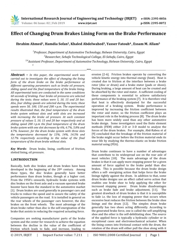
Professor, Department of Automotive Engineering, Helwan University, Cairo, Egypt International Research Journal of Engineering and Technology(IRJET) e-ISSN: 2395-0056 Volume: 06 Issue: 02 | Feb 2019 www.irjet.net p-ISSN: 2395-0072 Effect of Changing Drum Brakes Lining Form on the Brake Performance Ibrahim Ahmed1, Hamdia Sofan2, Khaled Abdelwahed3, Yasser Fatouh4 , Essam M. Allam5 1Professor, Department of Automotive Technology, Helwan University, Cairo, Egypt 2Researcher, Sehafa Technological College, El-Sehafa, Cairo, Egypt 3,4Assistant Professor, Department of Automotive Technology, Helwan University, Cairo, Egypt 5 ----------------------------------------------------------------------***--------------------------------------------------------------------- erosion [2-6]. Friction brakes operate by converting the vehicle kinetic energy into thermal energy (heat). Heat is created due to friction at the interface between a brake rotor (disc or drum) and a brake stator (pads or shoes). During braking, a large amount of heat can be created and be absorbed by the rotor and stator. A sufficient cooling of these components is essential to achieve satisfactory performance of the braking system [7]. It is therefore vital that heat is effectively dissipated for the successful operation of a braking system. Brake performance is improved by increasing the friction coefficient between the rotor and stator, so the friction coefficient plays an important role in the braking process [8]. The drum brake has been more widely used than any other automotive brake design. Some investigators used the finite element methods (FEM) either 2-D or 3-D model to analyze the forces of the drum brakes. For example, Abd-Rabou et al [9] concluded that the breakage of the friction material of the brake might occur before the friction material ends its wear life by studying the thermo-elastic on brake friction material using (FEA). Drum brake continues to have a number of advantages that contribute to its widespread use on the rear axle of most vehicles [10]. The main advantage of the drum brakes is that it can apply more stopping power for a given amount of force applied to the brake pedal than disc brakes. This is possible because the drum brake design offers a self- energizing action that helps force the brake linings tightly against the drum. In addition to that, some drum brake designs use an effect called servo action that enables one brake shoe to help applying the other for increased stopping power. Drum brake disadvantages such as brake fade and brake adjustment, [11]. The greatest drawback of drum brakes is that it is susceptible to fade i.e. the loss of stopping power that occurs when excessive heat reduces the friction between the brake shoe linings and the drum [12]. The simplex drum brake generally has two shoes acting differently. According to the generated brake force, one is called the self-amplifying shoe and the other is the self-debilitating shoe. The source of the applied force is typically a hydraulic cylinder or in exceptional cases and electromechanical actuator. When the lining comes into frictional contact with the drum, the rotation of the drum will either pull the shoe along with it Abstract –In this paper, the experimental work was carried out to investigate the effect of changing the lining form of the drum brake on the brake performance at different operating parameters such as brake oil pressure, sliding speed and the final temperature of the brake lining. All experimental tests are conducted in the same conditions 60 seconds of braking. Four brake oil pressures are selected during the tests; these values were 5, 10, 15 and 20 bar. Also, four sliding speeds are selected during the tests; these speeds were 50, 100, 150 and 200 r.p.m. The experimental results illustrated that, the final temperature of the drum brake system without slots and with slots are increased with increasing the brake oil pressure. At each constant pressure of values 5, 10, 15 and 20 bar respectively and at sliding speed 200 r.p.m the final temperature of the drum brake system with one slot decreases by 6%, 6.7%, 5.8% and 4.7%. however, for the drum brake system with three slots the temperatures decreased by 13%, 14%, 14.5% and 12.7% respectively according to the value of the final temperature of the drum brake without slots. Key Words: Drum brake, lining, coefficient of friction, slotted lining, oil pressure. 1.INTRODUCTION Basically, both disc brakes and drum brakes have been developed in the beginning of the 20th century. Among these types, the disc brakes generally have better performance than drum brakes, though at a higher cost. From the 1950's onwards, hydraulic brake systems with disc brakes on the front axle and a vacuum operated brake booster have been the standard in the automotive market [1]. Drum brakes are used generally in passenger cars and trucks to reduce the speed and to assure the safety of the vehicle passengers on the road. It is installed in general on the rear wheels of the passenger cars however, the disc brakes on the front wheels. The most advantage of the drum brake rather than disc is the self-energization of the brake that assists in reducing the required actuating force. Companies are seeking manufacturer parts of the brake system and the center for research to achieve the equation between the decline in the value of the coefficient of friction which leads to fade, and increase, leading to © 2019, IRJET | Impact Factor value: 7.211 | ISO 9001:2008 Certified Journal | Page 1
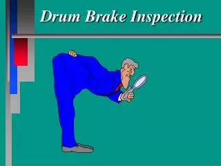
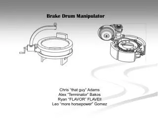
International Research Journal of Engineering and Technology(IRJET) e-ISSN: 2395-0056 Volume: 06 Issue: 02 | Feb 2019 www.irjet.net p-ISSN: 2395-0072 or push the shoe away, depending on the position of the shoe pivoting point relative to the direction of rotation. This action provides a form of self-amplification. The brake assembly in the drum brake is designed to be self-energizing that allows the shoe to mechanically increase the applied force through the hydraulic system and assist in the braking action. The increase is achieved by mounting the shoes to the backing plate in such a way that take advantage of frictional force that occurs when the brake lining contacts the rotating drum [13]. During drum rotation, the upper tips of the shoes are pushed apart by the expander force and a normal inward reaction force provided by the drum, resists any shoe expansion. Consequently, the drum slide over the shoe linings and a tangential frictional force is produced between each pair of rubbing surfaces. The friction force or drag on the left- hand shoe (primary shoe) tends to move in the same direction as the shoe tip force which produces it. Accordingly, this helps to drag the shoe onto the drum, so that the shoe tip force is raised effectively above that of the original expander force. This increase in shoe tip force above the input expander force is termed as positive servo, and shoes that provide this self-energizing or servo action are known as leading shoes or self-energizing shoes as mention by Khaled, [14]. Fig -1: Main components of the test rig. So, it was found that these studies were not conducted by studying the influence of slotted lining on the behavior or performance of the drum brake system. Taking into consideration that the Simplex drum brake system with the non-slotted lining and with one-slot and three slots lining and its effect on the performance of the brake. Hence, this paper will concentrate on this comparison between the different slotted linings and its effect on the brake performance at different boundary condition. 2. EXPERIMENTAL TESTS The main units of the brake test rig which is designed and constructed are shown in Figure (1). The brake test rig divided into the following main parts: • The brake system (Simplex drum brake) • The kinetic energy generation assembly. • The normal force generation unit. Fig – 2: Simplex (leading trailing) drum, [16]. The braking force will be calculated according to the consideration shown in Figure (3), [15]. By taking the moment about the point B, so; A drum brake of Suzuki Van is used in the test rig. This braking system is a simplex drum brake as mentioned previously. The main components of the simplex brake system are shown in Figure (2). It consists of leading shoe and trailing shoe with wheel cylinder which contains the hydraulic piston, braking plate, return springs and the brake linings. The simplex drum brake shown in Figure (2) is then simplified as shown in Figure (3) for each leading and trailing shoe, [15]. In simplex drum brake, the applied force is produced either by hydraulic cylinder, electromechanical actuator or by cam. Fa .(a + b) + Fb1 . C – Fn1 . a = 0 (1) Where Fb1 The braking force of the leading shoe, (N) Fn1 The normal force of the leading shoe, (N) Fa The applied force (piston force), (N) µ The coefficient of friction © 2019, IRJET | Impact Factor value: 7.211 | ISO 9001:2008 Certified Journal | Page 2
International Research Journal of Engineering and Technology(IRJET) e-ISSN: 2395-0056 Volume: 06 Issue: 02 | Feb 2019 www.irjet.net p-ISSN: 2395-0072 By substituting from equation (7) in equation (6) will give the following equation: Fa (a + b) - µ. Fn2 .C – Fn2.a = 0 (8) By arranging the previous equation will give the following equation: Fa (a + b) = Fn2.a + µ. Fn2 . C Fa (a + b ) = Fn2 .(a + µ.C ), so the normal reaction force (trailing shoe ) is : Fn2 = Fa ( a+b ) a+ µ .c By substituting from equation (9) in equation (7), so the braking force which produced by the trailing shoe will be: Fb2 = µ.Fa ( a+b ) a+µ c By comparing equations (4, 9) and (5, 10), it can be seen that, the brake force which is produced by the leading shoe is greater than the produced brake force by the trailing shoe at the same applied force. So, the simplex drum brakes use the generated force by friction to increase the clamping force (applied force) of the leading brake shoe, hence increasing the braking force of this shoe, [12]. The specifications of the main components of the used brake system are shown in the Table (1). The hydraulic line is connected between the normal force mechanism and the hydraulic piston of the wheel cylinder. (9) Fig -3: Force analysis of the simplex drum brake, [15]. The braking force or the normal force which produced by the leading shoe can be calculated from the following equation: Fb1 = µ. Fn1 (2) By substituting from equation (1) in equation (2) will give the following equation: Fa (a + b) + µ. Fn1 .C – Fn1. a = 0 (3) By arranging the previous equation will give the following equation: Fa (a + b) = Fn1.a - µ. Fn1 . C Fa (a + b) = Fn1 .(a - µ.C), so the normal reaction force (leading shoe) is: Fn1 = Fa ( a+b ) a− µ .c By substituting from equation (4) in equation (2), so the braking force which produced by the leading shoe will be: Fb1 = µ.Fa ( a+b ) a−µ c Similarly, for trailing shoe, by evaluating the moment about the point C will give the following equation: (10) Table -1: Specifications of the main components of the brake system. Component Value 220 mm 250 mm 216 mm 40 mm 5 mm 253 mm 42 mm 2 mm 140° 120° 24 mm Drum inner diameter Drum outer diameter Brake lining length Brake lining width Brake lining thickness Shoe length Shoe width Shoe thickness Shoe arc Lining arc Piston diameter (4) (5) The brake torque is considered the significant factor in this research on the brake system. There are two main methods to measure the brake torque either by torque transducer or by power meter. The torque transducer measures the braking torque directly. Also, there is another method which uses a power meter to measure the power consumption of the electric motor during the braking process which is used in this work. In this case, the sliding speed is also measured to determine the braking torque. The electric motor power was measured by using a digital power meter type Schneider PM 1200 Fa (a + b) – Fb2 . C – Fn2. a = 0 (6) The braking force or the normal force which produced by the trailing shoe can be calculated from the following equation: Fb2 = µ. Fn2 (7) Where Fb2 The braking force of the trailing shoe, N Fn2 The normal force of the trailing shoe, N © 2019, IRJET | Impact Factor value: 7.211 | ISO 9001:2008 Certified Journal | Page 3
International Research Journal of Engineering and Technology(IRJET) e-ISSN: 2395-0056 Volume: 06 Issue: 02 | Feb 2019 www.irjet.net p-ISSN: 2395-0072 which has range from 20 watt to 300 Kw and has accuracy 1% of reading for power as clear in Figure (1). The power meter measured the power of the electric motor during the braking process as the normal force affected the braking system. It also measured the no load power as there was no normal force affected the braking system. The no load power is the power which consumed from the electric motor to overcome the inertia forces of the test rig elements. In this study the brake power was determined as follow: Pb= PL−Pno(9) Where: Pb The brake power, (watt) PL The electric motor power at the braking process, watt Pno The electric motor power at no braking load, (watt) The rotational speed of the rotor drum (sliding speed) is also a very significant parameter in the braking process. The sliding speed of the braking system was measured by a digital tachometer which its type is (DT6234 B) and it has range from 5 to 100000 r.p.m with accuracy of 0.5 %. By calculating the brake power of the braking system at the braking process as mentioned previously in equation (9) and the angular speed of the rotating drum, the brake torque was calculated as follow; Tb= Pb ω = 2πn 60 (11) Where Tb The braking torque, (N.m) ω The angular speed of the rotating drum, (rad/sec) n The sliding speed of the rotating drum, (r.p.m) In this paper, the experimental work was carried out to investigate the effect of changing the lining form of the drum brake on the brake performance at different operating parameters such as brake oil pressure, sliding speed and the initial temperature of the brake lining. All experimental tests are conducted in the same conditions 60 seconds of braking. Four brake oil pressures are selected during the tests at 5,10,15 and 20 bar respectively. Also, four sliding speeds are selected during the tests at 50,100,150 and 200 r.p.m. The brake power which produced by the brake lining without slots, with one slot (which reduce the friction area by 1.5%) and with three slots (which reduce the friction area by 4.5%) were measured every second by the digital power meter. The sliding speed, the brake oil pressure, the final operating temperature were measured during each test. The brake force and friction coefficient of the drum brake were calculated every second and plotted with the brake time during each test. 3. RESULTS AND DISCUSSIONS Figures (4), (5) and (6) show the effect of brake oil pressure on the brake force of the drum brake system without and with slots at sliding speed of 200 r.p.m. It explained that, the brake forces of the drum brake system without and with slots are increased with increasing the brake oil pressure. The brake forces of the drum brake system fluctuate with no certain trend at each constant pressure with the brake time and this is due to the variation of the friction coefficient with the time. The presented results also in Figure (4), Figure (5) and Figure (6) show that, with the increase of the braking time, the brake force of the drum brake system without and with slots tend to decrease specially at high pressure. Due to the increase of the braking time, the friction temperature increases. Hence, the brake force tends to decrease as a result of friction coefficient decrease. The presented results in Figure (7) show the effect of the brake oil pressure on the mean brake force of the drum brake system without slots and with slots. The results showed that, the mean brake forces of the drum brake system without and with slots are increased with increasing the brake oil pressure. Also, the mean brake force of the drum brake system without slots is greater than the mean brake force of the drum brake system with slots at each pressure. This is because decreasing the friction area in the brake lining. The average mean brake forces of the drum brake system without slots are 188, 272, 466, 772 N and with one slot are 182, 264, 448, 742 N and with three slots are 174, 247, 420, 700 N respectively at brake oil pressure of 5, 10, 15 and 20 bar respectively too. At each constant pressure, the mean brake force of the drum brake system with one slot decreases by 3%, 3%, 3.6%, 3.8% under the average mean brake forces of the drum brake system without slots. Also the mean brake forces of the drum brake system with three slots decreases by 9%, 9.1%, 9.2%, 9.4% respectively under the mean brake forces of the drum brake system without slots. ω (10) 1000 P = 5 bar P = 15 bar P = 10 bar P = 20 bar 800 Brake force (N) 600 400 200 0 0 10 20 30 40 50 60 Time (sec) Fig – 4: Brake force against time for non-slotted lining at sliding speed 200 r.p.m at different brake oil pressure. © 2019, IRJET | Impact Factor value: 7.211 | ISO 9001:2008 Certified Journal | Page 4
International Research Journal of Engineering and Technology(IRJET) e-ISSN: 2395-0056 Volume: 06 Issue: 02 | Feb 2019 www.irjet.net p-ISSN: 2395-0072 1000 Figure (8) shows that, the mean friction coefficient of the drum brake system without slots is higher than the mean friction coefficient of the drum brake system with slots at each pressure. This is because decreasing the friction area in the brake lining, the normal force which affects the brake lining of the drum brake system (without slots) is greater than the normal force which affects the brake lining of the drum brake system (with slots) at the same pressure. This leads to increase the mean friction coefficient of the drum brake system (without slots) at each pressure. An increase of the oil pressure from 5 to 20 bar causes an increase on the mean friction coefficient from 0.263 to 0.33 for drum brake without slots. Another increase from 0.246 to 0.315 for drum brake with one slot will occur and from 0.227 to 0.28 for drum brake with three slots. 0.4 No slots One slot Mean friction coefficient P = 5 bar P = 15 bar P = 10 bar P = 20 bar 800 Brake force (N) 600 400 200 0 0 10 20 30 40 50 60 Time (sec) Fig – 5: Brake force against time for one-slotted lining at sliding speed 200 r.p.m at different brake oil pressure. 1000 Three slots P = 5 bar P = 15 bar P = 10 bar P = 20 bar 800 0.35 Brakeforce(N) 600 0.3 400 0.25 200 0.2 0 5 10 15 20 0 10 20 30 40 50 60 Pressure (bar) Time (sec) Fig – 8: Mean friction coefficient against pressure at sliding speed 200 rpm for number of lining slots. The effect of brake oil pressure on the final temperature of the drum brake system without slots and with slots at sliding speed of 200 r.p.m is presented in Figure (9). It explained that, the final temperature of the drum brake system without slots and with slots are increased with increasing the brake oil pressure. Also, the final temperature of the drum brake system without slots greater than the final temperature of the drum brake system with slots at each pressure. This is because decreasing the friction area in the brake lining. The final temperature of the drum brake system without slots and with slots, are shown in table (2). Table -2: The final temperature of the non-slotted and slotted lining at sliding speed of 200 r.p.m and different brake oil pressures. Fig – 6: Brake force against time for three-slotted lining at sliding speed 200 r.p.m at different brake oil pressure. 900 No slots One slot Three slots 800 700 Meanbrakeforce (N) 600 500 400 300 200 100 0 P = 5 bar P = 10 bar Pressure (bar) P = 15 bar P = 20 bar Fig – 7: Mean brake force against pressure at sliding speed 200 r.p.m for number of lining slots. Pressure Temperature T (°C) at No slots T (°C) at One slot T (°C) at Three slots P= 5 bar P= P= P = 20 bar 10 bar 74 15 bar Figure (8) shows the variation of the mean friction coefficient of the drum brake system without slots and with slots at sliding speed of 200 r.p.m at different brake oil pressures. It showed that, the mean friction coefficient of the drum brake system without slots and with slots are increased with increasing the brake oil pressure. Also, 46 103 126 43 69 97 120 40 63 88 110 © 2019, IRJET | Impact Factor value: 7.211 | ISO 9001:2008 Certified Journal | Page 5
International Research Journal of Engineering and Technology(IRJET) e-ISSN: 2395-0056 Volume: 06 Issue: 02 | Feb 2019 www.irjet.net p-ISSN: 2395-0072 1600 At each constant pressure, the final temperature of the drum brake system with one slot decreases by 6%, 6.7%, 5.8%, 4.7% and 13%, 14%, 14.5%, 12.7% respectively for the drum brake system with three slots compared to the final temperature of the drum brake without slots. 1200 Brake force (N) 800 400 140 No slots One slot Three slots N= 50 r.p.m N= 150 r.p.m N= 100 r.p.m N= 200 r.p.m 120 0 100 0 10 20 30 40 50 60 Temperature (℃) Time (sec) 80 60 Fig -10: Brake force against time for non-slotted lining at braking pressure 20 bar and at different sliding speeds. 40 20 0 P= 5 bar P= 10 bar pressure ( bar) P= 15 bar P= 20 bar 1600 1200 Fig -9: Temperature against pressure atsliding speed 200 r.p.m for number of lining slots. Brake force (N) 800 400 The effects of sliding speed of the rotating drum on the brake force of the drum brake system without slots and with slots at pressure of 20 bar is presented in Figure (10), Figure (11), and Figure (12). It can be concluded that, the brake forces of the drum brake system without slots and with slots fluctuate with no certain trend at each constant sliding speed with the braking time. The fluctuation of the brake force is due to the variation of the friction coefficient with the braking time. The results presented in Figure (13) show the variation of the mean brake force of the drum brake system without slots and with slots at different sliding speeds. From the results, it can be seen that the increase of the sliding speed of the rotating drum cause a decrease of the mean brake force of the drum brake system without slots and with slots. This decrease could be due to the decrease of the friction coefficient. The mean brake forces of the drum brake system without slots are 1436, 1038, 912, 766 N and the mean brake forces of the drum brake system with one slot are 1394, 991, 881, 737 N and the mean brake forces of the drum brake system with three slots are 1268, 929, 812, 691 N at sliding speeds of 50, 100, 150, 200 r.p.m respectively. Also, Figure (13) shows that, at each constant speed, the mean brake force of the drum brake system with one slot decrease approximately by 2.89%, 2.8%, 2.9%, 3% respectively, and for the drum brake with three slots decrease approximately by 8.4%, 9%, 10%, 9% respectively under the mean brake force of the drum brake system without slots. N= 50 r.p.m N= 150 r.p.m N= 100 r.p.m N= 200 r.p.m 0 0 10 20 30 40 50 60 Time (sec) Fig -11: Brake force against time for one-slotted lining at braking pressure 20 bar and at different sliding speeds. 1600 1200 Brake force (N) 800 400 N= 50 r.p.m N= 150 r.p.m N= 100 r.p.m N= 200 r.p.m 0 0 10 20 30 40 50 60 Time (sec) Fig -12: Brake force against time for three-slotted lining at braking pressure 20 bar and at different sliding speeds. © 2019, IRJET | Impact Factor value: 7.211 | ISO 9001:2008 Certified Journal | Page 6
International Research Journal of Engineering and Technology(IRJET) e-ISSN: 2395-0056 Volume: 06 Issue: 02 | Feb 2019 www.irjet.net p-ISSN: 2395-0072 final temperature of the drum brake system with one slot are 56, 69, 93, 120 °C and the final temperature of the drum brake system with three slots are 52, 63, 86, 110 °C at sliding speeds of 50, 100, 150, 200 r.p.m respectively as shown in Table (3). The increase of the sliding speed from 50 r.p.m to 200 r.p.m causes an increase on the final temperature of the drum brake system without slots by 117%. And the increase of the sliding speed from 50 r.p.m to 200 r.p.m causes an increase on the final temperature of the drum brake system with one slot by 114%. Also, the increase of the sliding speed from 50 r.p.m to 200 r.p.m causes an increase on the final temperature of the drum brake system with three slots by 111%. 1600 No slots One slot Three slots 1200 Mean brake force (N) 800 400 0 N= 50 r.p.m N= 100 r.p.m Sliding speed (r.p.m) N= 150 r.p.m N= 200 r.p.m 140 Fig -13: Mean brake force against sliding speed at oil No slots One slot Three slots pressure of 20 bar for number of lining slots. 120 100 0.6 Temperature(℃) 80 Mean friction coefficient 0.5 60 40 0.4 20 0.3 0 N= 50 r.p.m N= 100 r.p.m N= 150 r.p.m N= 200 r.p.m No slots One slot Three slots 0.2 Sliding speed (r.p.m) 50 100 150 200 Fig -15: Temperature against sliding speed at oil pressure of 20 bar for number of lining slots. Table -3: The final temperature of the non-slotted and slotted lining at oil pressure of 20 bar and different brake oil pressures. Sliding speed (r.p.m) Fig -14: Mean friction coefficient against sliding speed at oil pressure of 20 bar for number of lining slots. Figure (14) shows the effect of the sliding speeds of the rotating drum on the mean friction coefficient of the drum brake system without slots and with slots at brake oil pressure of 20 bar. The results indicated that, the increase of the sliding speed of the rotating drum cause a decrease of the mean friction coefficient of the drum brake system without slots and also with slots. The increase of sliding speed from 50 r.p.m to 200 r.p.m causes a decrease on the mean friction coefficient from 0.52 to 0.34 for the drum brake system without slots and from 0.506 to 0.318 for drum brake system with one slot and from 0.472 to 0.287 for drum brake system with three slots. The effects of sliding speed of the rotating drum on the final temperature of the drum brake system without slots and with slots at pressure of 20 bar is presented in Figure (15). The results presented in Figure (15) show the variation of the final temperature of the drum brake system without slots and with slots at different sliding speeds. From the results, it can be seen that the increase of the sliding speed of the rotating drum cause an increase of the final temperature of the drum brake system without slots and with slots. The final temperature of the drum brake system without slots are 58, 72, 98, 126 °C and the Speed Temperature T (°C) at No slots T (°C) at One slot T (°C) at Three slots N= N= N= N= 50 rpm 100 rpm 72 150 rpm 200 rpm 58 98 126 56 69 93 120 52 63 86 110 6. CONCLUSIONS The main conclusion from this work can be summarized as follows; •The brake force of the drum brake system without and with slots varies and fluctuates with no certain trend with the braking time due to the variation of the friction coefficient with the braking time. •The increase of the brake oil pressure increases the mean brake force of the drum brake system without slots and with slots (one slot reducing friction area 1.5% , three slots reducing friction area 4.5%). •The increase of the brake oil pressure of values 5, 10, 15, 20 bar respectively at sliding speed 200 r.p.m decreases the mean brake force of the drum brake © 2019, IRJET | Impact Factor value: 7.211 | ISO 9001:2008 Certified Journal | Page 7
International Research Journal of Engineering and Technology(IRJET) e-ISSN: 2395-0056 Volume: 06 Issue: 02 | Feb 2019 www.irjet.net p-ISSN: 2395-0072 7-Arthur Stephens "Aerodynamic cooling of Automotive Disc Brakes" M.Sc. thesis, School of Aerospace, Mechanical & Manufacturing Engineering, RMIT University, March 2006. 8-Giri, N.K. "Automobile Mechanics" Romesh Chandra Khanna for Khanna Publishers, 2007. 9-Abd-Rabou, M.M. and El-Sherbiny, M.G. "Thermo Elastic Study on Brake Pads Using FEA" Journal of Engineering Applied Science, Vol. 45, No 5, pp. 709719, 1998. 10-Halderman, J. D. "Automotive Technology: principles, diagnoses, and service" Pearson Education, Inc., 2009. 11-Nouby. M. Ghazaly and Mostafa. M. Makrahy "Experimental investigation Performance for passenger car" Proceedings of Theiier-Science Plus International Conference, Kuala Lumpur Malaysia. ISBN: 978-93-84209-57-5, 2014. 12-J. GreselleBalotin, Patric Daniel Neis and Ney Francisco Ferreira "Analysis of the influence of temperatures on the friction coefficient Universidad Federal do Rio Grande do Sul, 2010. 13-Arthur Stephens "Aerodynamic cooling of Automotive Disc Brakes" M.Sc. thesis, School of Aerospace, Mechanical & Manufacturing Engineering, RMIT University, March 2006. 14-Khaled A. K. "Improving the disc brake performance at high temperatures through modifying the brake system and designing an instructional unit of the theory of vehicle course for the third-year students at the faculty of industrial education according to the research results" PhD thesis, Helwan University, 2018. 15-Mahmoud, K. R. M. "Theoretical and experimental investigations on a new adaptive duo servo drum brake with high and constant brake shoe factor" PhD thesis, Heinz Nixdorf Institute, University of Paderborn, 2005. 16-Robert Bosch "Bremsanlagen für Kraftfahrzeuge" GmbH, Taschenbuch – Illustriert, 17. Oktober 1994 system with one slot by 3%, 3%, 3.6%, 3.8% . And 9%, 9.1%, 9.2%, 9.4% respectively for the drum brake system with three slots compared to the mean brake force of the drum brake without slots. •The increase of the sliding speed from 50 r.p.m to 200 r.p.m with step 50 r.p.m at brake oil pressure 5 bar decreases the mean brake force of the drum brake system, the mean brake force of the drum brake system with one slot decrease approximately by 2.89%, 2.8%, 2.9%, 3% respectively compare to the mean brake force of the drum brake without slots. •The increase of the sliding speed of values 50, 100, 150, 200 r.p.m decreases the mean friction coefficient of the drum brake system without slots and with slots. But at each speed the mean friction coefficient of the drum brake system without slots was higher than the mean friction coefficient of the drum brake system with slots. •The final temperature of the drum brake system without slots and with slots increased with increasing the brake oil pressure. At each constant pressure of values 5, 10, 15, 20 bar and at sliding speed 50 r.p.m decreases the final temperature of the drum brake system with one slot by 4%, 3.3%, 4.2%, 3.4%. And 8.3%, 9.6%, 12.7%, 10.3% respectively for the drum brake system with three slots compared to the final temperature of the drum brake without slots. of drum brake of friction materials" REFERENCES 1-H.P. "Comparative Frictional Analysis of Automobile Drum and Disc Brakes" Tribology in Industry, Vol. 38, No. 1, pp. 11-23, 2016. 2-Yehia Talkhan "Studying the Frictional behavior of disc brake system at different operating conditions and their effects on clarifying the importance of the practical demonstration teachers" A thesis M.Sc., 2017. 3-Ibrahim Ahmed “Modeling of Vehicle Drum Brake for Contact Analysis Using Ansys” SAE 2012 Brake Colloquium and Exhibition - 30th Annual, September 23-26, 2012, San Diego, California, USA, SAE 2012-01- 1810, 2012. 4-Ibrahim Ahmed, Essam Allam, Mohamed Khalil and Shawkil Abouel-seoud “Automotive Drum Brake Squeal Analysis Using Complex International Journal of Modern Engineering research (IJMER), Vol. 2, Issue 1, pp 179-199, Jan-Feb 2012. 5-Ibrahim Ahmed “Contact Behaviour of Vehicle Drum Brake by Using Finite Element Analysis” SAE Noise and Vibration Conference and Exhibitions 2007, Paper No. 2007-01-2264, SAE May 15-18, 2007. 6-Ibrahim Ahmed and S. Abouel Seoud “On the Analysis of Drum Brake Squeal Using Finite Element Method Technique” SAE 2006-01-3467, SAE 2006 Commercial Vehicle Engineering Congress & Exhibition, SAE, October 2006. Khairnar, V.M. Phalle and S.S. Mantha with the automotive BIOGRAPHIES Ibrahim Ahmed, is a Professor of Vehicle Dynamic and Control at Helwan University in Egypt. He is currently the Head of Production Technology Department. He obtained his B.Sc. (1990) and M.Sc. (1995) of Automotive Engineering from Helwan Unversity in Cairo, Egypt followed by another M.Sc. University of Technology, Netherlands, 1997. He obtained also the PhD (2002) from Newcastle Upon Tyne, UK. He has about 50 papers in the field of Vehicle Tribology and (NVH). Eigenvalue Methods” from Eindhoven The Dynamics, © 2019, IRJET | Impact Factor value: 7.211 | ISO 9001:2008 Certified Journal | Page 8
International Research Journal of Engineering and Technology(IRJET) e-ISSN: 2395-0056 Volume: 06 Issue: 02 | Feb 2019 www.irjet.net p-ISSN: 2395-0072 Hamdia Sofan is an Instructor at Industrial Technical Institute in El Sehafa, Technological Sehafa, Ministry of Higher Education in Egypt from 2009 till present. She received her B.Sc. Education (2005) and has experience for 4 years in teaching at Faculty of Industrial Education, University, Cairo, Egypt. College of of Industrial Helwan Khaled Abdelwahed is an Assistant Professor at Automotive Technology Department, Helwan University. He received his B.Sc. (1990) and M.Sc. from Eindhoven Technology (The Netherlands, 1997). In 2018 he received his Ph.D. in Automotive Technology from Faculty of Industrial Education, University, Cairo -Egypt. His research interest includes Technology and Development and Teaching Methods of Automotive Technology. Yasser Fatouh, Professor of Vehicle Dynamic and Control at Helwan University in Egypt. He obtained his B.Sc. (1992) and M.Sc. (1997) in Mechanical Engineering and PhD (2007) from Helwan University in Cairo, Egypt. He has many contributions in the field of Noise, Vibration and Harshness (NVH). University of Helwan Automotive Curriculum is an Assistant Design Essam M. Allam is a Professor of Vehicle Dynamic and control at Helwan University. He obtained the B.Sc., M.Sc. & PhD Automotive Engineering from Helwan University in 1995, 2001 & 2005 respectively. He publications in the field of Vehicle Dynamic and control. In addition his current research projects are focused on development of the vehicle noise and vibration from point of view of control and maintenance. degrees in has about 25 © 2019, IRJET | Impact Factor value: 7.211 | ISO 9001:2008 Certified Journal | Page 9