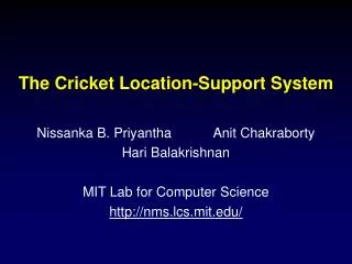
The Cricket Location-Support System
The Cricket Location-Support System Nissanka B. Priyantha Anit Chakraborty Hari Balakrishnan MIT Lab for Computer Science http://nms.lcs.mit.edu/ Motivation Emergence of pervasive computing environments Context-aware applications Location-dependent behavior


The Cricket Location-Support System
E N D
Presentation Transcript
The Cricket Location-Support System Nissanka B. Priyantha Anit Chakraborty Hari Balakrishnan MIT Lab for Computer Science http://nms.lcs.mit.edu/
Motivation • Emergence of pervasive computing environments • Context-aware applications • Location-dependent behavior • User and service mobility • Navigation via active maps • Resource discovery Cricket provides applications information about geographic spaces they are in
Design Goals • Preserve user privacy • Operate inside buildings • Recognize spaces, not just physical position • Good boundary detection is important • Easy to administer and deploy • Decentralized architecture and control • Low cost and power consumption
Controller/ Location database ID= u ? Base stations ID = u ? ID = u ? ID = u ? ID = u Transceivers Traditional Approach Centralized architecture User-privacy issues High deployment cost
Beacon Space C Space A Space B I am at C Listener Cricket Architecture Decentralized, no tracking, low cost Think of it as an “inverted BAT”!
RF data (locationname) Determining Distance Beacon • A beacon transmits an RF and an ultrasonic signal simultaneously • RF carries location data, ultrasound is a narrow pulse • Velocity of ultra sound << velocity of RF Ultrasound (pulse) Listener • The listener measures the time gap between the receipt of RF and ultrasonic signals • A time gap of x ms roughly corresponds to a distance of x feet from beacon
Uncoordinated Beacons Beacon A Beacon B • Multiple beacon transmissions are uncoordinated • Different beacon transmissions can interfere • Causing inaccurate distance measurements at the listener Incorrect distance RF B RF A US B time US A
Handling Spurious Interactions • Combination of three different techniques: • Bounding stray signal interference • Preventing repeated interactions via randomization • Listener inference algorithms
RF A US A t Bounding Stray Signal Interference • RF range > ultrasonic range • Ensures an accompanied RF signal with ultrasound
S/b t r/v (max) S r b v Bounding Stray Signal Interference S - size of space string b - RF bit rate r - ultrasound range v - velocity of ultrasound (RF transmission time) (Max. RF US separation at the listener)
Bounding Stray Signal Interference RF B US B RF A US A t • Envelop ultrasound by RF • Interfering ultrasound causes RF signals to collide • Listener does a block parity error check • The reading is discarded
Preventing Repeated Interactions • Randomize beacon transmissions: loop: pick r ~ Uniform[T1, T2]; delay(r); xmit_beacon(RF,US); • Erroneous estimates do not repeat • Optimal choice of T1 and T2can be calculated analytically • Trade-off between latency and collision probability
Inference Algorithms • MinMode • Determine mode for each beacon • Select the one with the minimum mode • MinMean • Calculate the mean distance for each beacon • Select the one with the minimum value • Majority (actually, “plurality”) • Select the beacon with most number of readings • Roughly corresponds to strongest radio signal
Inference Algorithms A Frequency B 5 Distance (feet) 5 10
Closest Beacon May Not Reflect Correct Space Room A Room B I am at B
Correct Beacon Positioning Room A Room B x x I am at A Position beacons to detect the boundary Multiple beacons per space are possible
Implementation • Cricket beacon and listener LocationManager provides an API to applications Integrated with intentional naming system for resource discovery
Implementation • Cricket beacon and listener RF RF Micro- controller Micro- controller RS232 US US LocationManager provides an API to applications Integrated with intentional naming system for resource discovery
Interference L2 L1 Static listener performance • Immunity to interference • Four beacons within each others range • Two RF interference sources • Boundary detection ability • L1 only two feet away from boundary Room A Room B % readings due to interference of RF from I1 and I2 with ultrasound from beacons I1 I2 Room C
Mobile listener performance Room A Room B Room C
Comparisons System Attribute
Summary • Cricket provides information about geographic spaces to applications • Location-support, not tracking • Decentralized operation and administration • Passive listeners and no explicit beacon coordination • Requires distributed algorithms for beacon transmission and listener inference • Implemented and works!
Preserves user privacy • Good granularity • Component cost U.S. $10
Beacon positioning Location X Imaginary Boundary X1 X2 X3 Imaginary boundaries Multiple beacons per location
Future work • Dynamic transmission rate with carrier-sense for collision avoidance. • Dynamic ultrasonic sensitivity. • Improved location accuracy. • Integration with other technologies such as Blue Tooth.
Inference algorithms • Compared three algorithms • Minimum mode • Minimum arithmetic mean • Majority
Minimizing errors. • Proper ultrasonic range ensures overlapping RF and ultrasonic signals • RF data 7 bytes at 1 kb/s bit rate • RF signal duration 49 ms • Selected ultrasonic range = 30ft < 49 ft • Signal separation < 49 ms
Minimizing errors. • Interfering ultrasound causes RF signals to collide • Listener does a block parity error check • The reading is discarded