Download
1 / 10
100 likes | 157 Views
https://www.gbic-shop.de/de/produkte/transceiver/sfpplus/kompatibel-5/10gbase-sr/extreme-networks-ex-enterasys-10gb-sr-sfpp-detail.html ...... <br><br>When optical transceiver was first expanded, establishing the performance of it was outspoken. The <br><br>complete network was authorized and owned by a single company, and if the system worked, thorough testing <br><br>of the subcomponents was irrelevant. <br><br><br><br>

E N D
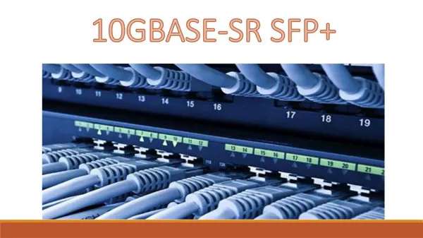
Extreme Networks 10GBASE-SR SFP+ Transceiver https://www.gbic-shop.de/de/produkte/transceiver/sfpplus/kompatibel-5/10gbase-sr/extreme-networks-ex-enterasys-10gb-sr-sfpp-detail.html
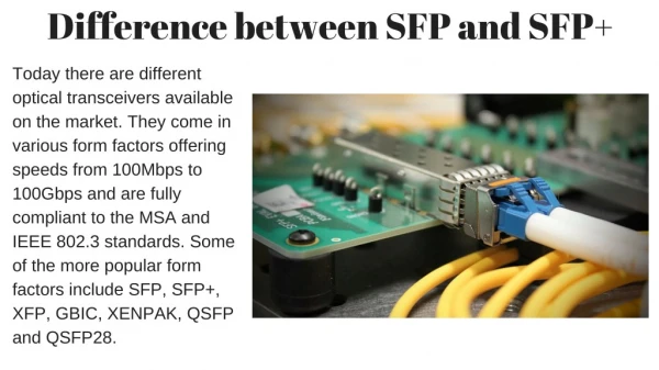
Introductions To Transceivers When optical transceiver was first expanded, establishing the performance of it was outspoken. The complete network was authorized and owned by a single company, and if the system worked, thorough testing of the subcomponents was irrelevant. Today, most optical networks use components that may come from different suppliers. Hence, to examine the adaptability of each fiber optic transceiver becomes especially significant.
How to test a fiber optic transceiver? A fiber optical transceiver consists of a receiver and the transmitter. When a transmitter connect to a receiver through a fiber but the system is not able to achieve desired bit-error-ratio (BER), both transmitter and the receiver is at fault. A low-quality transmitter can recoup by a low-quality receiver. You need to check the specifications and it needs to be assured that any receiver will interoperate with a worst-case transmitter, and any transmitter will interoperate with a worst-case receiver and provide a signal with to quality.
Specifically determining the worst case is often a complex task. If a receiver needs a minimum level of power to manage the system BER target, then that level will precept the minimum allowed output power of the transmitter. If the receiver can permit a reliable level of jitter, this will be used to define the highest acceptable jitter from the transmitter.
Specifically determining the worst case is often a complex task. If a receiver needs a minimum level of power to manage the system BER target, then that level will precept the minimum allowed output power of the transmitter. If the receiver can permit a reliable level of jitter, this will be used to define the highest acceptable jitter from the transmitter.
Transmitter testing: Transmitter parameters may include wavelength and shape of the output waveform. The receiver may specify tolerance to jitter and bandwidth. There are two steps to examine a transmitter: 1. The input signal used to test the transmitter must be good enough. Measurements of jitter and an eye mask test must be performed to confirm the quality using electrical measurements. An eye mask test is a common method to view the transmitter waveform and present a vast quantity of information about overall transmitter performance. 2. The optical output of the transmitter must be examined using several optical quality metrics such as an OMA (optical modulation amplitude), mask test, and Extinction Ratio.
Receiver Testing: To test a receiver, two steps are followed: 1. One must ensure that the input signal is of good enough quality, testing the receiver associated with sending a signal that is of poor enough quality. To do this, a stressed eye depicting the worst case signal shall be created. This is an optical signal, which needs to be calibrated using jitter and optical power measurements. 2. Finally, testing the electrical output of the receiver must be achieved. Three basic categories of tests must be performed: A mask test, which ensures a large enough eye opening. The mask test is usually conducted by a BER (bit error ratio) depth.
Three basic categories of tests must be performed: 1.Mask test: This kind of test ensures a large enough eye opening. The mask test is usually conducted by a BER (bit error ratio) depth. 2. Jitter budget test This type of test make sure to tests a number of certain types of jitter. 3. Jitter tracking and tolerance, It examines the efficacy of the internal clock recovery circuit to track jitter within its loop bandwidth.
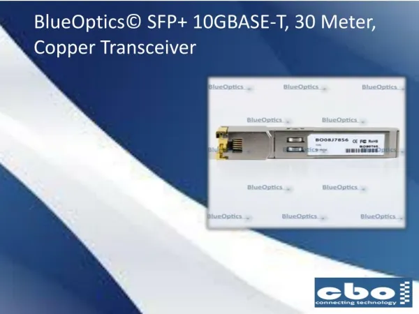
About 10GB-SR-SFPP • 10GB-SR-SFPP is an Enterasys® compatible 10GBase SFP+ Optical Transceiver and is factory preprogrammed with all the important configuration data for seamless network integration. Our transceivers operate identically to Enterasys® original transceivers and are 100% compatible with other OEM and third party transceivers. The 10GB-SR-SFPP is 100% MSA (Multi-Source Agreement) obedient.
Contact Us Email info@gbic-shop.de Phone +49 - 208 - 777 2478 - 0 Address Friedhofstraße 25, 45478 Mülheim an der Ruhr, Germany