Download
1 / 3
30 likes | 47 Views
4754/4751 Series Duplex Filters u2013 Coralonu00ae lube and hydraulic oil filters deliver consistent, high-level fluid system protection across all applications, regardless of severity. Coralon filters feature BetaX(C) >1000 filter efficiency, low-pressure drop, and long service life.

E N D
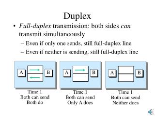
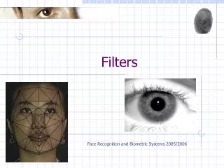
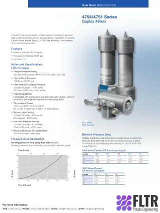
Data Sheet M&E4754/51EN 4754/4751 Series Duplex Filters Coralon® lube and hydraulic oil filters deliver consistent, high level fluid system protection across all applications, regardless of severity. Coralon filters feature BetaX(C)>1000 filter efficiency, low pressure drop and long service life. Features • Flows to 340 lpm (90 US gpm) • Pressures to 450 bar (6500 psi) • Port size: 1½” Notes and Specifications Filter Housing • Fatigue Pressure Rating 400 bar (5800 psi) per NFPA T2.6.1 R2-2001 Cat C/90 • Typical Burst Pressure: 1,600 bar (23,200 psi) • Filter Element Collapse Pressure: 10 bard (150 psid) – 4754 series 207 bard (3000 psid) – 4751 series • Fluid Compatibility: Compatible with all petroleum oils and most water glycols, water-oil emulsions, and synthetic hydraulic and lubricating fluids • Temperature Range: -29 ˚C to 120 ˚C (-20 ˚F to 250 ˚F) 60 ˚C (140 ˚F) maximum in HWCF or water glycols • Bypass Valve Setting: 3.4 bard (50 psid) – 4754 series Non-bypass – 4751 series • Indicator Pressure Setting: 2.4 bard (35 psid) – 4754 series 7 bard (100 psid) – 4751 series • Housing Materials of Construction: Ductile iron head; steel bowls 4754 Series Filter Housing Element Pressure Drop Multiply actual flow rate times factor in table below to determine pressure drop with fluid at 32 cSt (150 SUS), 0.9 S.G. Correct for other fluids by multiplying new viscosity in cSt/32 (SUS/150) x new S.G./0.9. Pressure Drop Information Housing pressure drop using fluid with 0.9 S.G. Housing pressure drop is directly proportional to specific gravity. Flow (L/min) 4704 Series Element DP Factors (psid/gpm) 0 100 200 300 Length 8” 13” 16” CP 0.20 0.12 0.09 CS 0.12 0.07 0.05 CZ 0.46 0.27 0.20 CN 0.17 0.10 0.07 CT 0.09 0.05 0.04 20 1.5 15 1.0 10 9601 Series Element DP Factors (psid/gpm) P (bard) P (psid) 0.5 5 Length 8” CP 0.52 CS 0.30 CT 0.12 0 0 13” 16” 0.32 0.25 0.18 0.14 0.08 0.07 0 20 40 60 80 100 Flow (US gpm) For more information: WEB WEB: FLTR.com.au PHONE PHONE: (+61) 1300 62 4020 EMAIL EMAIL: info@FLTR.com.au SKYPE SKYPE: Purple.Engineering
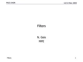
Ordering Information For new installations, select one complete part number from each section below Section 1 Housing P/N: Note: Pall filter housings are supplied without filter elements or filter change out warning devices. Never operate the filter housing unless a filter element is fitted and all warning device ports are sealed. Section 3 Differential Pressure Indicator P/N: RC Z 097 Z Table 4 Table 5 Housing part number designates indicator port is fitted with a plastic shipping plug. Note: If no Differential Pressure Indicator is selected, ‘B’ type blanking plug (P/N HC9000A104Z) must be ordered separately and fitted to replace the shipping plug. Note: Z indicates fluorocarbon seals are standard. Other options are available; contact Pall. Part Number HZ4754A24SB1 HZ4754A24TB1 HZ4754A24UB1 HZ4754E24SB1 HZ4754E24TB1 HZ4754E24UB1 HZ4751A24SW1 HZ4751A24TW1 HZ4751A24UW1 HZ4751E24SW1 HZ4751E24TW1 HZ4751E24UW1 Table 4:Indicator Options Code A218M Brass Option Indicator Electrical switch (SPDT) with Hirschmann connector Electrical switch (SPDT) with Hirschmann connector with Red and Green LED indicators A218R Part Number (Description) Breakdown HZ = housing with fluorocarbon seals 4754 = 4754 series housing 4751 = 4751 series housing (high collapse element) A24 = 1½” SAE J514 straight thread port E24 = 1½” Flange ports SAE J518C code 62 (414 bar/6000 psi max pressure) S = 8” nominal length T = 13” nominal length U = 16” nominal length W = Non-bypass 1 = 1 indicator warning device port A219D Visual indicator Code 778N Stainless Steel Option Indicator Visual filter with thermal lockout 861C Electrical switch (SPDT) with Hirschmann connector 771B Electrical switch (SPDT) with 3-pin Table 5:Differential PressureIndicator Material Code Omit Description If Brass Indicator is selected in Table 4 If Stainless Steel Indicator is selected in Table 4 (recommended for high pressure applications with pressure > 200 bar (3000 psi) SS Section 2 Element P/N: HC F Z Table 2 Table 3 Table 1 Table 1:Element Options Description Code 10 bard (150 psid) – for 4754 series 207 bard (3000 psid) – for 4751 series 4704 9601 Table 2:4704 Series Filter Performance Ratings Coralon Filter Grade ISO Code Rating per Stress- Resistance Test (80% ∆p)* ßx(c) ≥1000 per ISO 16889 10/08/03 12/09/07 14/11/06 15/11/06 16/14/08 CZ CP CN CS CT 3 5 7 12 22 * based on 60 psid terminal pressure drop Table 2 - 9601 Series Filter Performance Ratings Code ßx(c) ≥1000 per ISO 16889 5 12 15 CP CS CT Table 3: Length Options Code Description 8 13 16 8” nominal length 13” nominal length 16” nominal length For more information: WEB WEB: FLTR.com.au PHONE PHONE: (+61) 1300 62 4020 EMAIL EMAIL: info@FLTR.com.au SKYPE SKYPE: Purple.Engineering
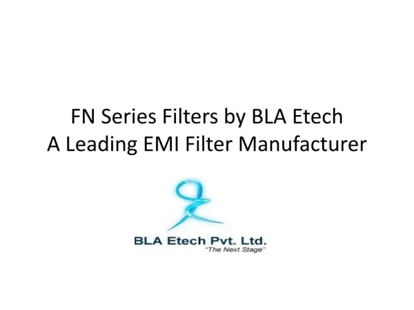
Dimensional Drawings Dimensions in mm (inches) MIN CLEARANCE REQUIRED FOR ELEMENT REMOVAL 70 mm (2.76 in) 136 mm (5.35 in) S = 210 mm (8.3 in) T = 330 mm (13.0 in) U = 430 mm (17.0 in) 33 mm (1.30 in) KNURLED HAND GRIP TYP 2 PLACE S = 220 mm (8.7 in) T = 342 mm (13.5 in) U = 442 mm (17.4 in) 148 mm (5.83 in) 26 mm (1.02 in) 106 mm (4.17 in) 188 mm (7.40 in) 44 mm (1.73 in) DIM. “H” SEE INDICATOR SECTION 140 mm (5.51 in) 115 mm (4.53 in) 113 mm (4.45 in) 49 mm (1.93 in) 110 mm (4.33 in) 78 mm (3.07 in) 116 mm (4.57 in) 220 mm (8.66 in) OUTLET 5”-11UNC-2B THREAD TO BS 1580 X 24 MIN FULL THREAD 100 mm (3.94 in) .25” The equipment has been assessed in accordance with the guidelines laid down in The European Pressure Directive 97/23/EC and has been classified within Sound Engineering Practice S.E.P. Suitable for use with Group 1 and 2 fluids only. Consult Sales for other fluid gas group suitability. For more information: WEB WEB: FLTR.com.au PHONE PHONE: (+61) 1300 62 4020 EMAIL EMAIL: info@FLTR.com.au SKYPE SKYPE: Purple.Engineering