Download
1 / 8
0 likes | 1 Views
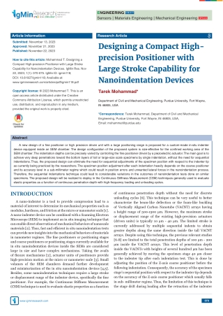
A new design of a fine positioner or high precision driven unit with a large positioning range is proposed for a custom-made in-situ indenter device equipped inside an SEM chamber. The design configuration of the proposed system is size-effective for the confined working area of the SEM chamber.

E N D
ENGINEERING SUBJECT Sensors | Materials Engineering | Mechanical Engineering TOPIC(S) A Multidisciplinary Open Access Journal ISSN: 2995-8067 Article Information Research Article Submitted: November 13, 2023 Designing a Compact High- precision Positioner with Large Stroke Capability for Nanoindentation Devices Approved: November 21, 2023 Published: November 22, 2023 How to cite this article: Mohammad T. Designing a Compact High-precision Positioner with Large Stroke Capability for Nanoindentation Devices. IgMin Res. Nov 22, 2023; 1(1): 070-075. IgMin ID: igmin118; DOI: 10.61927/igmin118; Available at: www.igminresearch.com/articles/pdf/igmin118.pdf Tarek Mohammad* Copyright license: © 2023 Mohammad T. This is an open access article distributed under the Creative Commons Attribution License, which permits unrestricted Department of Civil and Mechanical Engineering, Purdue University, Fort Wayne, use, distribution, and reproduction in any medium, IN 46805, USA provided the original work is properly cited. *Correspondence: Tarek Mohammad, Department of Civil and Mechanical Engineering, Purdue University, Fort Wayne, IN 46805, USA, Email: mohammat@purdue.edu Abstract A new design of a fine positioner or high precision driven unit with a large positioning range is proposed for a custom-made in-situ indenter device equipped inside an SEM chamber. The design configuration of the proposed system is size-effective for the confined working area of the SEM chamber. The indentation depths can be precisely varied by controlling the fine positioner driven by a piezoelectric actuator. The main goal is to achieve very deep penetrations toward the bottom layers of tall or large-size scale specimens by single indentation, without the need for sequential indentations. Thus, the proposed design can eliminate the need for sequential adjustments of the specimen position with respect to the indenter tip as currently being practiced by the researchers. The specimen position adjustment after each indentation heavily depends on the coarse positioner and its accuracy level in a sub-millimeter regime which could result in position errors and unwanted lateral forces in the nanoindentation process. Therefore, the sequential indentations technique could lead to considerable variations in the outcomes of nanoindentation tests done on similar specimens. The proposed design will be realized to deploy in the Continuous Stiffness Measurement (CSM) techniques generally used to evaluate elastic properties as a function of continuous penetration depth with high-frequency loading and unloading cycles. INTRODUCTION of continuous penetration depth without the need for discrete unloading cycles [6]. This technique can be very useful to better characterize the beam-like defl ection or the foam-like buckling of Vertically Aligned Carbon Nanotube (VACNT) arrays having a height range of 500-1500 μm. However, the maximum stroke or displacement range of the existing high-precision actuators (driven units) is typically 10 μm - 40 μm. The limited stroke is currently addressed by multiple sequential indents to obtain greater depths along the same direction inside the tall VACNT arrays. Despite using this technique, the previous relevant studies [6-8] are limited to the total penetration depths of 100 μm - 200 μm inside the VACNT arrays. This level of penetration depth inside the VACNTs with heights of several hundred μm has been generally achieved by moving the specimen stage 40 μm closer to the indenter tip after each indentation test. This is done by adjusting the position of the Z-axis coarse positioner before the following indentation. Consequently, the accuracy of the specimen stage’s sequential position with respect to the indenter tip depends on the accuracy of the Z-axis coarse positioner which usually falls in sub- millimeter regime. Thus, the limitation of this technique is the stage drift during loading after the retraction of the indenter A nano-indenter is a tool to provide compression load to a material of interest to determine its mechanical properties such as modulus, hardness, and friction at the micro or nanometer scale [1]. A nano-indenter device can be combined with a Scanning Electron Microscope (SEM) to implement an in situ imaging technique that can enable direct observation of mechanical behaviors of nanoscale materials [2]. Thus, fast and effi cient in situ nanoindentation tests can provide new insights into the mechanical behaviors of materials in nanometer regimes. The fi ne positioners or positioning stages and coarse positioners or positioning stages currently available for in situ nanoindentation devices inside the SEMs are considered large in size and have complex mechanisms. Taking the avails of fl exure mechanisms [2], actuator units of positioners provide high-precision motion at the micro or nanometer scale [3]. Small volumes of the SEM chambers demand further development and miniaturization of the in situ nanoindentation devices [4,5]. Besides, some nanoindentation techniques require a large stroke or displacement range of the indenter device, specifi cally the fi ne positioner. For example, the Continuous Stiff ness Measurement (CSM) technique is used to evaluate elastic properties as a function 070 www.igminresearch.com
DOI: 10.61927/igmin118 ISSN 2995-8067 tip during proceeding unloading. This stage drift can change the position of the indenter tip on a micro or nanometer scale from its original position along the indentation path inside the specimen. This may also lead to unwanted lateral forces on the specimen during the stage position adjustment. Therefore, it is important to develop a compact nanoindentation device capable of long stroke (up to 1 mm) with high force and displacement resolutions so that tall specimens or a large number of samples assembled together can be tested continuously in a shorter amount of time, without introducing unwanted lateral forces. An excellent combination of mechanical [9], thermal [10], and electrical [11] properties makes Carbon Nanotubes (CNTs) promising in numerous applications that require lightweight, energy-effi cient, and high-strength materials. Consequently, it is important to defi ne and understand the characteristics of CNTs so that they can be properly utilized for their applications. The mechanical behaviors of Vertically Aligned Carbon Nanotube (VACNT) arrays, also known as CNT forests, in response to an axial compressive load, depend on successive bending as well as the density and alignment of the nanotubes [12]. Elastic properties of CNTs can be derived from the force- displacement relationship obtained through the nanoindentation process [13]. Design considerations Due to the lack of real-time observation during the indentation process, the understanding of mechanical behaviors of nanoscale materials is often limited to post-indentation deformation analysis [17]. As a result, these are usually related to the investigation of stress-strain relationships and comparison with relevant theoretical models. When it comes to the mechanics of VACNT arrays under compression, such post-indentation analysis may lead to inaccurate prediction of the deformation and recovery [17]. Therefore, a nanoindentation device can be combined with a Scanning Electron Microscope (SEM) to implement an in situ imaging technique. This technique can enable direct observation of buckling formation and propagation of VACNT arrays of diff erent heights. A few studies [12,17,18] have reported the infl uence of CNT array height over several orders of magnitude on mechanical yield strength. This proposed design is based on the technique that allows for axial compression on CNT arrays of diff erent heights by utilizing fl at punch indenter tips inside an SEM chamber. Flat surface indenter tips simplify the computation of stress compared to indenter tips having spherical or angular geometries. Metrics of interest for the indentation tests include axial and lateral buckling, elastic stiff ness and plastic deformation in CNT arrays observed in situ SEM imaging technique. The objective of this work is to develop a new design concept of a compact, high precision driven unit for an in situ nanoindentation device capable of long stroke (up to 1 mm) along the indentation axis with nano-newton force and nanometer displacement resolutions. This can be used to realize axial penetration of an intender tool to a tall specimen or a large number of samples assembled together, with relative ease and high-frequency loading and unloading cycles. The miniaturized driven unit can be easily integrated into the small working area of an SEM chamber for direct observation. Such a new device can facilitate a better understanding of the mechanical properties or behaviors of nanoscale materials with large-length scale structures and various morphologies. An experimental study [17], using in situ SEM nanoindentation technique, shows that the VACNT arrays shorter than 10 μm demonstrate elasticity even at high compressive strain (80% - 90%) whereas the VACNT arrays taller than several hundred micrometers demonstrate a plastic deformation upon the application of much less strains (~15%). The shorter arrays with highly aligned and weakly interacting CNTs demonstrate deformation geometry (beam-like defl ection) according to the Euler-Bernoulli column or beam theory [19]. On the other hand, tall VACNT arrays with highly entangled morphology demonstrate sequential buckling formation where the buckles are fi rst formed at the bottom side and then at the top surface of the arrays. The Euler- Bernoulli column theory is therefore not suffi cient to represent this behavior (foam-like buckling) due to the entangled morphology and strong van der Waals interactions between neighboring CNTs [20]. Thus, in situ observation enables us to evaluate the diff erent buckling modes and possibly explain their sequence inside the tall VACNT arrays. Then the observed deformation can be compared with the several proposed models [21,22] considering yield strengths dependency on height, vertical alignment, and density profi le of CNTs morphology. A new concept of the novel high precision driven unit with extended stroke and compact size is proposed for the in situ nanoindentation technique. This can be achieved by means of an Amplifi ed Piezoelectric Actuator (APA) confi guration [14], without compromising the high force and motion resolutions. In an APA, a piezoceramic stack is usually housed inside a compact, shell- like fl exure mechanism. The fl exural shell provides a preload to the piezoceramic stack. The piezoceramic stack provides actuation in the lateral direction which in turn amplifi es the desired motion of the APA in the longitudinal direction to several hundred micrometers. The small dimensions of the APA structures make them suitable for the small working area of the SEM chambers. The proposed high precision driven unit based on an Amplifi ed Piezoelectric Actuator (APA) will enhance the displacement range of the existing indenters used for in situ nanoindentation tests. A nanoindentation device equipped with this compact size driven unit will enable new experimental observations through its extended stroke during nanoindentation tests on various materials, which would have not been possible before because of the limited stroke and force capabilities of the existing Atomic Force Microscope (AFM) based [15] and Microelectromechanical System (MEMS) based techniques [16]. Many commercial indentation products utilize electromagnetic motors which are typically large in size. In addition, electro- magnetic interference aff ects the overall quality of the SEM images. Electrostatic actuation is also commonly used to realize high high-precision motion of the indenters. Although electrostatic actuators can provide compact size and fast response, they have limited force and displacement capabilities. Piezoelectric actuators can off er large force generation along with high force (in the nano- newton range) and motion (in the nanometer range) resolutions. IgMin Research in ENGINEERING 071 November 22, 2023 Volume 1 Issue 1
DOI: 10.61927/igmin118 ISSN 2995-8067 artifi cial skins, energy-absorbing materials, lighter aircraft frames, and wind turbine blade coatings [6]. Piezoelectric actuators can be housed inside fl exure mechanisms (Figure 1) which can provide the required compressive load to the actuators. Flexure hinges can provide precise displacement during actuation while overcoming the limitations of mechanical bearings and slides. However, such piezoelectric actuation confi gurations have limited strokes (only a few tens of μm) and are often considered large in size for the nano-indenters. The proposed long-stroke nano-indenter device can be a versatile tool for in situ nanoindentation tests on various nanoscale materials that have great potential as engineered structures for a number of future applications. By eliminating the position errors and unwanted lateral forces during the specimen position adjustment for the sequential nanoindentation process, the proposed design with long- stroke capability can address the discrepancy in the compressive elastic modulus values as reported in similar experimental studies. The accurate formation and propagation of buckling of tall VACNTs and CNT composites during nanoindentations will signifi cantly improve the understanding of their collective mechanical properties. Thus, this proposed system can potentially contribute to better designs of CNT-based structures for applications such as In addition to potentially improved nanoindentation tests on tall VACNT arrays, the proposed device can be used for mechanical tests on protein fi bers and fi brils which may lead to a better understanding of their mechanics. Collagen is a type of protein and is one of the key components of human bone, tooth dentin and blood vessels [23]. Due to the diffi culty in sample isolation, preparation, and handling, nanoindentation tests on single collagens often lead to dehydration and uncertainty in the estimation of their biomechanical properties [24]. For more accurate results with relative ease, it is desired to have the tests done on multiple fi brils integrated into larger-scale structures with lengths of hundreds of microns [25,26]. Thus, the proposed device with extended stroke and large force capabilities can lead to a better understanding and biomechanical modeling of collagen mechanics. This can in turn potentially contribute to improved therapies for osteoporosis and genetic disease. METHODOLOGY A. Precision-driven unit This design considers the small working area of the SEM chamber as well as the confi guration of the indenter, motorized positioning stages, load sensor, and displacement sensor. A previous design [17] of in situ nanoindentation device has dimensions of 103 mm × 47 mm × 60 mm as illustrated in Figure 1. Similarly, the proposed system has dimensions of 100 mm × 70 mm × 40 mm so that it can be easily integrated to the SEM chamber for eff ective in situ observation of the indentation region. The proposed precision- driven unit is composed of a compact actuator unit to provide driving force, an L-bracket to rigidly fi x the actuator unit with the coarse positioner, and a U-bracket to connect the actuator unit to the specimen stage through the load sensor. In addition, the force accuracy of this type of nanoindenter system largely depends on the linearity of the actuating spring. The lack of linear stiff ness of the actuating spring can cause considerable variations in results from nanoindentation tests done on similar specimens due to loading errors. As shown in Figure 1, the previous design utilizes a compact fl exure mechanism with hinges to provide accurate and precise displacement through the linear springs. Thus, precision driving and size miniaturization become possible to realize. This proposed driven unit also utilizes a fl exure mechanism taking advantage of its ability to provide accurate and precise linear displacement in a compact size format. In this design, a rhombus-shaped fl exure mechanism is used to magnify the precise displacement of the linear springs as illustrated in Figure 2. As a result, this proposed system can provide a maximum displacement of 1130 μm which is almost 10 times greater than the maximum displacement (11.4 μm) provided by the previous design [17]. B. Actuator unit The actuator unit is usually required to provide high force resolution and linear displacement resolution in the nanoscale. In the previous design, a piezoceramic stack is placed inside the Figure 1: Prototype of the previously developed in situ nanoindentation device consisted of a precision-driven unit and an indenter unit (reproduction from [20]). IgMin Research in ENGINEERING 072 November 22, 2023 Volume 1 Issue 1
DOI: 10.61927/igmin118 ISSN 2995-8067 1131 μm at the applied voltage of 150V as illustrated in Figure 4. In addition, the maximum stress is found as 49.83 MPa at the fl exure hinges which is signifi cantly less than the ultimate tensile strength A36 steel of 550 MPa. A nanoindentation process starts after placing a specimen in the stage. A commercial APA product, APF710 manufactured by Thorlabs [8], can be used as the actuator unit for this design confi guration. The APA has spring stiff ness of 0.04 N/μm and can provide a maximum pulling force of 55 N which is suffi cient for most of the nanoindentation tests. As the APA pulls its free end upon the application of voltage, the attached U-bracket pushes the stage towards the indenter unit. Thus the high precision driven unit precisely moves the stage with respect to the stationary indenter and to realize precise loading and unloading of the indenter inside the specimen during tests. This high precision-driven unit can be manipulated in a relatively long-range by a Z-axis coarse positioner. During the indentation, the load to the CNTs by the displacement of the indenter is measured by the load sensor. Due to the stiff ness diff erence between the actuator unit and the specimen, the measured displacement is not the real penetration depth inside the CNTs. However, the measured load is the real penetration load to the CNTs. The design described here can be set up using instruments commonly available in research laboratories as illustrated in Figure 5. The performance specifi cations of the proposed system greatly match with reference values obtained from the nanoindentation techniques on similar tests. Figure 2: Amplified piezoelectric actuator (APF710®) by Thorlabs [10]. fl exure mechanism in series, and a compressive load is applied to the stack through a preload screw as shown in Figure 1. As a result, both the piezo stack and fl exure provide the precision driving along the same axis, i.e., the indentation direction. Thus, the fl exure mechanism can precisely move the attached stage in the plane with respect to the indenter and realize precise loading and unloading of the indenter. This proposed design utilizes an amplifi ed piezoelectric actuator (APA) confi guration to realize precise linear motion with nanometer-level displacement and nano-newton-level force resolutions. The piezoceramic stack is housed inside the fl exure mechanism in parallel as shown in Figure 2. The proposed actuator unit has dimensions of 100 mm × 18 mm × 10 mm. The fl exural shell provides a preload to the piezoceramic stack so that it does not suff er from backlash. The fl exural shell has two ends or faces in the middle of its two lever arms. One of the ends is rigidly fi xed so that the other end is free to move through which the stack displacement can be amplifi ed and transformed. Upon the application of voltage, the stack provides the actuation in the lateral direction which in turn amplifi es the desired motion of the APA lever arms in the longitudinal direction several times. As a result, the proposed actuator unit has long-stroke ability with a relatively simple and compact structure realized by the APA confi guration. A nanoindentation device equipped with this compact size- driven unit will enable up to 1 mm of penetration depth in a single indentation (Figure 6). There will be no need for sequential C. Assembled confi guration Two metal brackets are used to integrate the proposed actuator unit into the whole system. As shown in Figure 3, the actuator unit is rigid and fi xed to the Z-axis coarse micro-positioning stage through a L-bracket. Subsequently, the free end of the actuator unit is attached to the load sensor through a U-bracket. To form the high-precision driven unit, the load sensor is attached to the stage upon which the specimen is placed. Through the Z-axis coarse positioner, the proposed driven unit can be further attached to the indentation device base which can be tilted with respect to the stage of the SEM in order to obtain a good observation angle. Figure 3: Model of the proposed high precision driven unit. Simulation results and potential impact A fi nite element analysis of the proposed high precision driven unit is performed by using ANSYS® software to ensure the necessary linear displacement of the unit. The fl exure model is made of steel A36 which has a density of 7800 kg/m3, Young’s modulus of 200 GPa, Poisson’s ratio of 0.26, and a shear modulus of 75 GPa. From the FEA analysis, the maximum linear displacement of the precision-driven unit along the indentation axis is found to be Figure 4: Finite element analysis of proposed high precision driven unit showing linear motion of stage provided by APA. IgMin Research in ENGINEERING 073 November 22, 2023 Volume 1 Issue 1
DOI: 10.61927/igmin118 ISSN 2995-8067 REFERENCES 1. Oliver DJ, Bradby JE, Williams JS, Swain MV, Munroe P, Journal of Applied Physics. 2009; 105:126101. 2. Mohammad T, Salisbury SP. An improved stiffness model for piezo- actuated complementary clamp flexures International Journal of Mechatronics and Automation. 2012; 2:4. 3. Mohammad T, Salisbury SP. Design and Assessment of a Z-Axis Figure 5: Schematic of the prospective experimental setup for the long-stroke nanoindentation device equipped with the proposed driven unit. Precision Positioning Stage with Centimeter Range Based on a Piezoworm Motor, in IEEE/ASME Transactions on Mechatronics. 2015; 20:5; 2021-2030. 4. Nowak JD, Malyska KA, Major RC, Warren OL, Michler J. Mater. Today. 2009; 12:44. 5. Ghisleni R, Rzepiejewska-Malyska K, Philippe L, Schwaller P, Michler J. In situ SEM indentation experiments: instruments, methodology, and applications. Microsc Res Tech. 2009 Mar;72(3):242-9. doi: 10.1002/ jemt.20677. PMID: 19140164. 6. Li Y, Kim HI, Wei B, Kang J, Choi JB, Nam JD, Suhr J. Understanding Figure 6: Expected output displacement curve of the proposed high precision driven unit. the nanoscale local buckling behavior of vertically aligned MWCNT arrays with van der Waals interactions. Nanoscale. 2015 Sep 14;7(34):14299-304. doi: 10.1039/c5nr03581c. PMID: 26242771. adjustments of the specimen position with respect to the indenter tip after each indentation which could result in position errors and unwanted lateral forces in the nanoindentation process. Thus faster and more reliable experimental observations through its extended stroke during nanoindentation tests on Vertically Aligned Carbon Nanotube (VACNT) arrays having a height range of 500 μm - 1500 μm will be very useful to better characterize the beam-like defl ection or the foam-like buckling of the arrays. CONCLUSION 7. Maschmann MR, Zhang Q, Wheeler R, Du F, Dai L, Baur J. In situ SEM observation of column-like and foam-like CNT array nanoindentation. ACS Appl Mater Interfaces. 2011 Mar;3(3):648-53. doi: 10.1021/ am101262g. Epub 2011 Mar 2. PMID: 21366265. 8. Maschmann MR, Zhang Q, Wheeler R, Du F, Dai L, Baur J. In situ SEM observation of column-like and foam-like CNT array nanoindentation. ACS Appl Mater Interfaces. 2011 Mar;3(3):648-53. doi: 10.1021/ am101262g. Epub 2011 Mar 2. PMID: 21366265. 9. Treacy MJ, Ebbesen TW, Gibson JM. Nature. 1996; 381:6584. 10. Panzer MA, Zhang G, Mann D, Hu X, Pop E, Dai H. Heat Transfer. The elastic properties of VACNT arrays with diff erent heights are evaluated by applying axial compressive loads through fl at punch nanoindentations. The direct observations enable new insights into the beamlike and foam-like deformations of the CNT arrays as a function of array height. The infl uence of array morphology on the deformations is also observed through this technique. The previous studies are limited to the total penetration depths of 100-200 μm due to the limited stroke of the actuator units used for the indenter instruments. The successive insertion and retraction of the indenter tip along with sequential adjustment of the specimen position can be used to achieve deeper penetration inside the tall CNT arrays having a height range of 500 μm - 1100 μm. However, this technique may result in some variations in the natural formation of localized buckling modes and their sequential evolution with strain upon continuous loading. 2008; 130:5. 11. Yaglioglu O, Hart J, Martens R, Slocum A. Rev. Sci. Instrum. 2006; 77:9. 12. Shen ZL, Dodge MR, Kahn H, Ballarini R, Eppell SJ. Stress- strain experiments on individual collagen fibrils. Biophys J. 2008 Oct;95(8):3956-63. doi: 10.1529/biophysj.107.124602. Epub 2008 Jul 18. PMID: 18641067; PMCID: PMC2553131. 13. Cao A, Dickrell PL, Sawyer WG, Ghasemi-Nejhad MN, Ajayan PM. Super-compressible foamlike carbon nanotube films. Science. 2005 Nov 25;310(5752):1307-10. doi: 10.1126/science.1118957. PMID: 16311330. 14. Thorlabs. APF710 actuator manual. https://www.thorlabs.com/drawings/ a5af8e2a348979c1-E33CCEFE-CABF-3FDB-3F3B6B8FEC9B1420/ APF710-Manual.pdf 15. Svensson RB, Hassenkam T, Hansen P, Peter Magnusson S. Viscoelastic behavior of discrete human collagen fibrils. J Mech Behav Biomed Mater. 2010 Jan;3(1):112-5. doi: 10.1016/j.jmbbm.2009.01.005. Epub 2009 Feb 3. PMID: 19878908. Most of the existing nanoindentation systems have limitations in terms of size, stroke, and force capabilities. To address these limitations, a new concept of novel high precision driven units with extended stroke and compact size is proposed for the in situ nanoindentation technique. This can be achieved by means of an amplifi ed piezoelectric actuator confi guration, without compromising the high force and motion resolutions. The small dimensions of the APA structures make them suitable for the small working area of the SEM chambers. The proposed high precision driven unit will enhance the displacement range of the existing indenters used for in situ nanoindentation tests. 16. Shen ZL, Dodge MR, Kahn H, Ballarini R, Eppell SJ. Stress- strain experiments on individual collagen fibrils. Biophys J. 2008 Oct;95(8):3956-63. doi: 10.1529/biophysj.107.124602. Epub 2008 Jul 18. PMID: 18641067; PMCID: PMC2553131. 17. Maschmann MR, Zhang Q, Wheeler R, Du F, Dai L, Baur J. In situ SEM observation of column-like and foam-like CNT array nanoindentation. ACS Appl Mater Interfaces. 2011 Mar;3(3):648-53. doi: 10.1021/ am101262g. Epub 2011 Mar 2. PMID: 21366265. 18. Maschmann MR, Zhang Q, Wheeler R, Du F, Dai L, Baur J. In situ SEM observation of column-like and foam-like CNT array nanoindentation. ACS Appl Mater Interfaces. 2011 Mar;3(3):648-53. doi: 10.1021/ am101262g. Epub 2011 Mar 2. PMID: 21366265. IgMin Research in ENGINEERING 074 November 22, 2023 Volume 1 Issue 1
DOI: 10.61927/igmin118 ISSN 2995-8067 19. Tong T, Zhao Y, Delzeit L, Kashani A, Meyyappan M, Majumdar A. 23. Nalla RK, Stölken JS, Kinney JH, Ritchie RO. Fracture in human cortical Height independent compressive modulus of vertically aligned carbon bone: local fracture criteria and toughening mechanisms. J Biomech. nanotube arrays. Nano Lett. 2008 Feb;8(2):511-5. doi: 10.1021/ 2005 Jul;38(7):1517-25. doi: 10.1016/j.jbiomech.2004.07.010. PMID: nl072709a. Epub 2008 Jan 12. PMID: 18189439. 15922763. 20. Ruoff RS, Tersoff J, Lorents DC, Subramoney S, Chan B, Nature. 24. Poissant J, Barthelat R. Exp. Mech. 2012; 52:9. 1993; 367:6437. 25. Hulmes DJ, Wess TJ, Prockop DJ, Fratzl P. Radial packing, order, 21. Bedewy M, Meshot E, Guo H, Verplogen E, Lu W. Phys. Chem. 2009; and disorder in collagen fibrils. Biophys J. 1995 May;68(5):1661-70. 111:16. doi: 10.1016/S0006-3495(95)80391-7. PMID: 7612808; PMCID: PMC1282067. 22. Huang H, Zhao H, Mi J, Yang J, Wan S, Xu L, Ma Z. AIP Advances. 2012; 2:012104. 26. Huan Y, Liu D, Yang R, Zhang T. Measurement. 2010; 43:1090. How to cite this article: Mohammad T. Designing a Compact High-precision Positioner with Large Stroke Capability for Nanoindentation Devices. IgMin Res. Nov 22, 2023; 1(1): 070-075. IgMin ID: igmin118; DOI: 10.61927/igmin118; Available at: www.igminresearch.com/articles/pdf/igmin118.pdf IgMin Research in ENGINEERING 075 November 22, 2023 Volume 1 Issue 1
INSTRUCTIONS FOR AUTHORS APC In addressing Article Processing Charges (APCs), IgMin Research: STEM recognizes their signi?icance in facilitating open access and global collaboration. The APC structure is designed for affordability and transparency, re?lecting the commitment to breaking ?inancial barriers and making scienti?ic research accessible to all. IgMin Research | STEM, a Multidisciplinary Open Access Journal, welcomes original contributions from researchers in Science, Technology, Engineering, and Medicine (STEM). Submission guidelines are available at www.igminresearch.com, standards and comprehensive author guidelines. Manuscripts should be submitted online to submission@igminresearch.us. emphasizing adherence to ethical IgMin Research - STEM | A Multidisciplinary Open Access Journal fosters cross-disciplinary communication and collaboration, aiming to address global challenges. Authors gain increased exposure and readership, connecting with researchers from various disciplines. The commitment to open access ensures global availability of published research. Join IgMin Research - STEM at the forefront of scienti?ic progress. For book and educational material reviews, send them to STEM, IgMin Research, at support@igminresearch.us. The Copyright Clearance Centre’s Rights link program manages article permission requests via the journal’s website (https://www.igminresearch.com). Inquiries about Rights link can be directed to info@igminresearch.us or by calling +1 (860) 967-3839. https://www.igminresearch.com/pages/publish-now/author-guidelines https://www.igminresearch.com/pages/publish-now/apc WHY WITH US IgMin Research | STEM employs a rigorous peer-review process, ensuring the publication of high-quality research spanning STEM disciplines. The journal offers a global platform for researchers to share groundbreaking ?indings, promoting scienti?ic advancement. JOURNAL INFORMATION Journal Full Title: IgMin Research-STEM | A Multidisciplinary Open Access Journal Journal NLM Abbreviation: IgMin Res Journal Website Link: https://www.igminresearch.com Category: Multidisciplinary Subject Areas: Science, Technology, Engineering, and Medicine Topics Summation: 173 Organized by: IgMin Publications Inc. Regularity: Monthly Review Type: Double Blind Publication Time: 14 Days GoogleScholar: https://www.igminresearch.com/gs Plagiarism software: iThenticate Language: English Collecting capability: Worldwide License: Open Access by IgMin Research is licensed under a Creative Commons Attribution 4.0 International License. Based on a work at IgMin Publications Inc. Online Manuscript Submission: https://www.igminresearch.com/submissionor can be mailed to submission@igminresearch.us