Download
1 / 14
140 likes | 918 Views
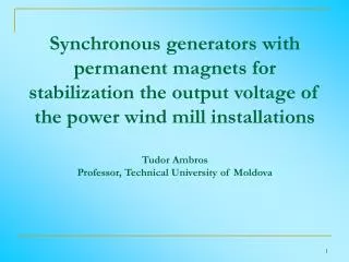
Synchronous generators with permanent magnets for stabilization the output voltage of the power wind mill installations Tudor Ambros Professor, Technical University of Moldova 1. Introduction

E N D
Synchronous generators with permanent magnets for stabilization the output voltage of the power wind mill installationsTudor AmbrosProfessor, Technical University of Moldova
1. Introduction At the given stage, the wind power even more often is used as a source of electrical energy. On the open places, on the sea, where speed of a wind is high and rather constant, the main indicators of energy quality, voltage and frequency of a source of a current are constant. In zones as, for example, in Republic of Moldova, which is situated in a pool of the Black Sea, the velocity of a wind is variable and not high. From these reasons, the basic element of transformation of a mechanical wind power in electrical energy - electrical generator is necessary for adapting to the parameters of the electrical motor of low velocity. The mechanical construction of those motors, as generators, should ensure constant frequency and voltage on output at variable velocity of a wind. The maintenance of a constancy of frequency and voltage can be realized by electronic devices. But for independent generators of small capacity used in agriculture, in places remote from electrical networks, the electronic devices are becoming unprofitable because of dearness and complexity of service. The decision of this problem offered in the given paper is based on use the synchronous generators with permanent magnets.
There are two variants of synchronous generators with permanent magnets: the first, when the revolutions velocity of the wind mill motor is higher than 500 rev/min and second variant, when the speed is less than 500 rev/min. In both cases these generators have the following advantages: • Absence of electrical contact of sliding; • Increased value of the efficiency ratio and power factor; • Increased reliability; • Lowered reaction of an rotor. • The basic lacks of these generators: • Variable frequency of a current; • Difficulty of regulation or stabilization of a voltage. In a case, when consumer the kind of a current (alternating or direct) does not interest, the problem is reduced to regulation or stabilization of a voltage. If the velocity of the wind mill generator is higher than 500 rev/min, it is possible to use, as the synchronous generator, the asynchronous standard motor, on a rotor of which are mounted the permanent magnets and at the stator's winding is connected the controlled rectifier (fig. 1).
Fig.1. The synchronous generator with controlled rectifier In the offered scheme, the generator of an alternating current is transformed into the generator of a direct current, however controlled rectifier complicates the device of a source of a direct current and does not justify itself on low powers. Other decision, concerning stabilization of a voltage on terminals of the synchronous generator with constant magnets, can be realized by pre-magnetization of the yoke of a stator by direct current and replacement of the controlled rectifier by unguided (fig.2). Fig.2. The synchronous generator with pre-magnetization yoke of a stator and uncontrolled rectifier
The winding of a pre-magnetization Wp, which covers the stator's yoke and through which flows the direct current, provides stabilization of a voltage on output of stator's winding W1 by pre-magnetization or un-magnetization of the stator's yoke. The magnetization force created by a current of a winding of pre-magnetization Ip, is subtracted or is summarized with the magnetization forces of permanent magnets and reaction of a stator: - magnetization force created by winding of pre-magnetization and by permanent magnets; - magnetization force created by three phases winding and by permanent magnets; If the design of the generator contains 2р of poles, then yoke of a stator is divided on 2р of sectors (fig. 3). Alternately, the sectors are magnetized and are unmagnetized. If the sectors of magnetization are sated, their magnetic resistance is increasing, total magnetic working flow is decreasing and e.m.f., output voltage, on the terminals of the generator is decreasing.
On the unmagnetized sectors a flow Fig.3. Magnetization and unmagnetization of the stator's yoke In formulas (1-2), Rp - magnetic resistance of the magnetizing sectors and Rd - magnetic resistance of unmagnetizing poles. The total resistance of the magnetizing sectors lpJ - length of a sector, Sj - cross section of the yoke.
Taking into account, that the force of magnetizing it is possible by regulation the value of the current Ip , is possible, by regulation the current Ip, to maintain constant the voltage on the terminals of generator at different change of the load and frequency of rotation of the generator. This fact is explained, that the magnetic flow created by is closed only on yoke, in that time when are closed on an air gap.When the frequency of rotation of the wind mills engine is low, it is necessary to execute the generator with the large number of poles, that in a cylindrical construction is difficult to execute, or it is possible to execute the generator with small number of poles and connect its with wind mills engine through a multiplier. A multiplier raises cost and reduces the efficiency of device as a whole. In replacements of that is offered at the n≤500 revolution per min to connect with wind mills motor the synchronous generator with constant magnets and axial air gap which is calculated on 2р>12. Most suitable is the synchronous generator with constant magnets and with two rotors, which has the small axial and large radial sizes, and can be executed with plenty of poles, i.e. on low speeds (fig. 4). and are closed on an air gap.
The technology of stacking of a three-phase winding and pre magnetization winding is identical, as these windings are toroidal and together enveloped the yoke of stator and practically they are presenting one winding. The basic advantages of the generator: - the frontal parts of a stator winding are reduced approximately twice; - a plenty of poles reduce frequency of rotation; - big moment of inertia, which smooths frequency of rotation at variable load; - increased surfaces of cooling. For studing the process of magnetization and unmagnetization of the stator's yoke the method of final elements was used. Fig. 4. A general view of the axial generator: 1 - blades; 2 - disk of a rotor; 3 - core; 4 - windings; 5 - box of terminals; 6 - permanent magnets; 7 - fixing ledges
In fig.5 is shown the picture of a magnetic field created by permanent magnets, the magnetic lines of which are closing through poles. a b c Fig. 5. Distribution of the created magnetic flow: а) by permanent magnets; б) by current of the stator Is; с) by current of magnetization winding Ip The magnetic force lines of a flow of stator's reaction are closing in space between poles, where the magnetic resistance is less. The magnetic flow of pre magnetization is closing through yoke, where the magnetic resistance is also less. In fig.6 the pictures of magnetic fields created by permanent magnets, stator's current and current of pre-magnetization (fig.6,a) are submitted. The picture of a magnetic field of permanent magnets and field, imposed on it by the stator's reaction of armature (fig.6,b) practically does not differ from a figure of a field shown on fig. 6,а, as the reaction of an armature is insignificant.
At imposing a field of permanent magnets (fig. 6,с) and magnetic field of pre- magnetization current, the common picture of a field considerably changes. In a fig.7 are shown the results of computation of a picture of a magnetic field of the axial generator without slots on a stator with a three-phase toroidal winding stacked on yoke. The forces lines of a magnetic induction are distributed in regular intervals in the yoke of a stator of the generator, which represents one half from common yoke of the generator The curve distributions of a magnetic induction in an air gap (fig.8,а), as well as curve of distribution of an induction in a yoke of the stator, do not contain high harmonics. The absence of high harmonics is caused by absence of teeth on a stator and closeness of the permeability of permanent magnets to the magnetic permeability of air. a b c Fig. 6. A picture of magnetic fields distribution : а) at imposing a field of permanent magnets, reaction of armature and field of pre magnetization, б) field created by permanent magnets, с) at imposing a field of permanent magnets and field of pre magnetization
Fig. 7. A picture of a magnetic field of the synchronous axial generator without slots on a stator with a three-phase toroidal winding Having changed a configuration of poles, it is possible to receive a sinusoidal curve of induction distribution in an air gap. a b Fig. 8. Curve distributions of a magnetic induction: а) in an air gap, b) in an yoke of stator
2. Conclusions • By magnetizing the stator's yoke of the synchronous generator with permanent magnets it is possible to stabilize the output voltage of the generator. • For the generator with a toroidal winding, the frontal parts of a three-phase winding are reduced. • The generator with an axial rotor can be executed on small frequencies of rotation