USB
USB. USB = Universal Serial Bus Industry-led open standard USB Implementers Forum USB-IF Intel, Microsoft, HP, Compaq… Evolution USB 1.0 (1996) USB 1.1 (1998) USB 2.0 (2000). Why USB?. Shortcomings of existing PC IO: Scarcity of PC HW resources (IRQ and DMA channels, IO space)

USB
E N D
Presentation Transcript
USB • USB = Universal Serial Bus • Industry-led open standard • USB Implementers Forum USB-IF • Intel, Microsoft, HP, Compaq… • Evolution • USB 1.0 (1996) • USB 1.1 (1998) • USB 2.0 (2000) ET4508_p13 (KR)
Why USB? • Shortcomings of existing PC IO: • Scarcity of PC HW resources (IRQ and DMA channels, IO space) • Serial Port/Parallel Port: Single point-to-point connections • Diversity of connectors and cables. • Non hot-pluggable. Non-PnP • Poor data bandwidth • Cost of cables / connectors • No power delivery through interface ET4508_p13 (KR)
Why serial? Why not parallel? • Advantages of serial buses: • Signal IntegrityFewer coinciding signal transitions. Less crosstalk. Less noise. Less inter-signal skew. • CostDrivers, connectors, cables, receivers • Disadvantage of serial buses: • Higher clock-rates required for given bandwidth ET4508_p13 (KR)
External Bus Options BANDWIDTH DEVICE COST APPLICATIONS ATTRIBUTES STD FEATURE Very Low cost Ease of Use Lots of fanout LOW 10 - 100Kb/s $5-25 1997 Input Devices Control Functions USB MEDIUM 200K - 10Mb/s $15-150 1997 Telephony/ Modem Audio, Scanner Low cost Guaranteed latency 1394A for CE HIGH 100 - 400Mb/s $100-500 TBD Entertainment, A/V Imaging Peer-to-peer Multiple channels 1394B Gigabit COMPUTE 1+ Gb/s $200-500 1999+ Primary Disk Home Backbone Very High bandwidth Fiber capability USB Focus on Low Cost,High Volume Applications USB Ver 2.0 Supports 480Mb/s ET4508_p13 (KR)
PC Connectivity Vision USB USB USB USB in 1996: Initially introduced as an incremental connector for new applications. USB Keyboard Serial Port Sound/Game Ports Modem LAN Mouse Parallel Port Graphics Port SCSI Port USB Future: The PC evolves into a simpler, easier to use appliance. Telephony, Modem, Kyb, Mouse, Joystick, Still/ Motion Camera, Digital Audio, Backup Store, Printer, Scanner, Wireless Adaptors Graphics Port LAN ET4508_p13 (KR)
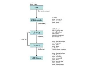
Universal Serial Bus (USB) - Introduction • Complex, hierarchical standard • Requires software layers both on the host computer and on the USB device • Serial Protocol and Physical Link • Hierarchy: PC is the host • Upstream points towards the host • Downstream points away from the host ET4508_p13 (KR)
Introduction (2) • Data transmitted serially • Data transmitted differentially on a pair of wires (D+ and D-) • 2 other wires are used to supply power to USB devices • USB devices may be Bus Powered or Self-Powered • USB includes specs on power consumption and voltage drops etc ET4508_p13 (KR)
2 Types of USB Cable • High Speed Cables • Shielded, jacketed - use twisted pair wiring • Support max data rates of 12Mb/s • Support Cable lengths of 5m • Low Speed cables • Not shielded, pairs not twisted, cheaper • Support 1.5Mb/s • Support Cable lengths of 3m ET4508_p13 (KR)
Power pair Differential Signal pair USB Connectors • Connectors • 4-Position with shielded housing • Positive Retention • Blind Mating Capabilities • Cables • 28 AWG twisted pair for signalling • 20-28 AWG pair for power • Shielding for fully rated segments ET4508_p13 (KR)
Type A & B connections Type A Connector connects to Upstream Ports Type B Connector connects to Downstream Ports Each USB Cable has a Type A & Type B Connector ET4508_p13 (KR)
Power Distribution • Significant capability of USB • Eliminate wall adaptors • Hubs may be self-powered or bus-powered • Two current levels: 100 & 500 mA • Overcurrent protection for safety • Wire gauge options: 20-28 AWG ET4508_p13 (KR)
Data Signalling • Bi-directional, half-duplex link • Embedded clock and dataNRZI = Non Return to Zero, InvertedNRZI with Bit Stuffing • Differential signal pair ET4508_p13 (KR)
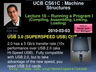
USB Bandwidth • USB 1.0 / 1.1 • 12 Mb/s Full Speed (FS) bit rate • 1.5 Mb/s Low Speed (LS) bit rate • USB 2.0 (May 2000) • additionally: 480 Mb/s High Speed (HS) • Applications: USB HDD. Video ET4508_p13 (KR)
Twisted Pair Shielded Untwisted, Unshielded Connections and Terminations R2 D+ D+ F.S./L.S. USB Transceiver F.S. USB Transceiver R1 D- (45ΩOutputs) ZO = 90Ω±15% 5 Meters Max. (45Ω Outputs) D- Hub Port 0 or Full Speed Function R1 Host or Hub Port R1 = 15KΩ±5% R2 = 1.5KΩ±5% D+ D+ F.S./L.S. USB Transceiver L.S. USB Transceiver R1 R2 D- (45Ω Outputs) 3 Meters Max. (45Ω Outputs) D- R1 R1 = 15KΩ±5% R2 = 1.5KΩ±5% Host or Hub Port Low Speed Function ET4508_p13 (KR)
DifferentialDriver D+ Xmt Data Force SE0 OE D- DifferentialReceiver + Rcv Data - SE0Detect Single-Ended Receivers USB Transceiver • Differential Driver • Slew rate controlled • SE0 drive capability • Differential Receiver • Sensitivity <200mV • Common mode range: < 1.0V to > 3.0V • Single-Ended Receivers • Threshold: 0.6V - 1.5V ET4508_p13 (KR)
Tiered Star Topology ET4508_p13 (KR)
Tiered Star Topology • Tiered Star Topology • Distributed connectivity points • Up to 6 Tiers • Up to 5m cable length per segment • Up to 127 Devices ET4508_p13 (KR)
Hosts, Hubs, Devices • Only one host per system – usually the PC • Host (Root Hub) is the USB system master • Controls and schedules all communications • Hubs are communication nodes that interconnect devices • Peripherals controlled by the USB bus are slaves that respond to host commands • Peripherals are called USB devices or functions ET4508_p13 (KR)
Hubs • USB Devices themselves • Bridges that increase logical and physical fan-out of the network • Single Upstream connection • To Root Hub (host) or next hub nearer host • One or more downstream connections • Hubs detect connection/removal of USB devices – Topology Changes ET4508_p13 (KR)
Downstream Connectivity Upstream Connectivity Hub Repeater Hub Repeater Disabled Port Enabled Ports USB Hub Function • Port Control • Connection detect • Port Enable/ Disable • Reset/ Resume Signaling • Data Switch • Signal Regeneration • Robustness/ Recovery • Power Distribution ET4508_p13 (KR)
Enumeration • Process that occurs when a new peripheral is connected to the USB network • Host communicates with the peripheral to find out what device driver is needed • Host supplies a device address during enumeration • Hence no switches to set up addresses ET4508_p13 (KR)
Hubs in logical connection • After Enumeration the hub becomes logically invisible to the application • Application code sees a logical connection directly from the host to each USB device ET4508_p13 (KR)
USB Pipes • USB Communication uses the idea of a Pipe • The USB connection consists of a big pipe (12Mb/s) and up to 127 small pipes • Each of the small pipes connects to a USB device • Each small pipe can connect to a smaller pipe (tiny pipe) – up to 16 tiny pipes per small pipe ET4508_p13 (KR)
Addresses and Endpoints • USB Token has 7 address bits per USB device • Address 0 – USB Default address is used for all devices when first attached • Hence 127 USB Devices (small pipes) • 4 Endpoint bits in a USB token allow up to 16 pairs of tiny pipes per small pipe • Endpoint 0 – just for Control transfers • USB Tokens also identify IN or OUT direction • 15 bi-directional sources or receivers of data per USB Device – identified by Endpoints ET4508_p13 (KR)
USB Pipes and Endpoints • All USB transfers occur through virtual pipes associated with Endpoints • Each Pipe may have different bandwidth and may require different types of data transfer • Each endpoint associated with a descriptor • Type of Data Transfer • Max size of data packets • Interval for transfer, bandwidth needed etc ET4508_p13 (KR)
Endpoints • Device may have a number of endpoints • E.g. Different Endpoint (and pipe) for • Data • File transfers – low error rate necessary • Voice • Error tolerant but not delay tolerant • Control • Low error rate but lower data rate ET4508_p13 (KR)
Actual communications flow Logical communications flow Implementation Focus Area Basic USB Model Host Interconnect Device Capability Function Client SW Provides common device abstraction USB Logical Device USB Sys SW USB Bus USB Bus Physical Interface, Signalling Interface Interface ET4508_p13 (KR)
Three layers in USB model • Layers: • Function • USB Device • USB Bus Interface Layers • Comments: • Based on 7-layer OSI Model • Entities at the same layer have a virtual “peer-to-peer” connection • Entities at lower layers provide services to entities at next higher layer • Progressively hides details from higher layers ET4508_p13 (KR)
USB Host Layers • USB Bus Interface • Physical interface to wire • Manages low-level protocol • USB System Software • Provides interfaces to driver layers • Manages standard device objects • Client Software • E.g. device drivers • Manages capability ET4508_p13 (KR)
USB Device Layers • USB Bus Interface • Physical interface to wire • Manages low-level protocol • USB Logical Device • Defines common view of device by host • Manages high-level protocol • Function • Represents capability delivered bythe device ET4508_p13 (KR)
Host Device Function Client SW manages an interface a collection of Interfaces Interface x Endpoint 0 - Required, shared - Configuration access - Capability control Pipe Bundle to an interface No USB Format Interface Specific No USB Format Buffers USB Device USB System manages devices Endpoint Zero a collection of endpoints Default Pipe to Endpoint Zero USB Framed Data Unspecified Data Per Endpoint Data USB Bus Interface USB Bus Interface Host Controller USB Framed Data SIE SIE Transactions USB Wire Pipe, represents connection abstraction between two horizontal layers Data transport mechanism USB-relevant format of transported data Detailed Host/Device View ET4508_p13 (KR)
Client Software <-> Function Client Software Host Buffers Data Flows Pipes Endpoints USB Device Interface ET4508_p13 (KR)
USB Data Transfer Types • USB supports four transfer types: • Control • Bulk • Interrupt • Isochronous ET4508_p13 (KR)
Transfer Type Control • Control • Exchange configuration, set-up and command information between the device and the host • CRCs are used for error checking as error-free transmission is critical • Re-transmission initiated when errors are detected • Control endpoints are implemented on Endpoint 0 pair • Control transfer has 2 or 3 stages: setup stage, optional data stage, status stage ET4508_p13 (KR)
Transfer Type Bulk • Bulk Transfers • Large amounts of data where data is not time-critical • Error free transfer important hence CRC error-checking implemented • Claim unused bandwidth when nothing more important is going on • Typical applications: scanners, printers ET4508_p13 (KR)
Transfer Type Interrupt • Interrupt • Not interrupts in normal sense! • Unidirectional - only inputs to the host • Small data transfers that occur infrequently • Host polls polls interrupt endpoints to see if they have any data to send • Full speed devices: 1ms - 255ms polling • Low speed devices: 10ms - 255ms • Error checking validates the data • Mice and keyboards ET4508_p13 (KR)
Transfer Type Isochronous • Isochronous • Unidirectional or bidirectional • For time sensitive information, e.g. audio or video streaming • System must be able to tolerate some errors • No time for error checking • Guaranteed access to USB with bounded latency • No Retries • Max packet size for isochronous transfer is 1023B/frame • Max isochronous bandwidth is 8.184Mb/s ET4508_p13 (KR)
Communication Layers (1) • Frame • Time between SOF tokens = 1ms • Consists of a series of transactions • Transfer • One or more transactions to move data between client software and the function • Packet • Bundle of data organised in a set format for transmission • Types – Token, Start of Frame, Data, Handshake, HS/LS Preamble • Typically has Control information, Data to be transferred and Error detection and correction ET4508_p13 (KR)
Communication Layers (2) • Transaction • Grouping of no more than 3 packets • Host initiates a token packet according to schedule • PID identifies transaction type
USB Packets – 4 types • Packet • Bundle of data organised in a set format for transmission • Typically has Control information, Data tobe transferred and Error detection and correction • Token • SOF (Start of Frame) • Data • Handshake • HS/LS Preamble (optional) • All packets have • Sync field to lock the Phase Locked Loop • Followed by Packet Identifier (PID) • Also address, frame number or data ET4508_p13 (KR)
Token Packet ET4508_p13 (KR)
Packet Identifier ET4508_p13 (KR)
SOF Packet SOF packets are sent by the host once every 1.00ms +/- 0.05ms ET4508_p13 (KR)
Data Packet Devices respond to requests from the Host Host sends an IN and device endpoint responds with a packet OR Host sends an OUT followed by a data packet Bulk, Control, Interrupt: host responds with an Acknowledge Isochronous: no handshake packet ET4508_p13 (KR)
Handshake Packet Special Packet Host sends a PRE (preamble) packet when it wants to communicate with 1.5Mb/s devices ET4508_p13 (KR)
Slot Frame = 1ms BULK Low Speed Stereo Audio Low Speed BULK Stereo Audio BULK Stereo Audio BULK Stereo Audio BULK Stereo Audio BULK Stereo Audio BULK Stereo Audio BULK Stereo Audio BULK Stereo Audio BULK Stereo Audio (not to scale) Interrupt, Control, Low Speed SOF Rx Voice Scanner Tx Voice Rx Line Tx Line USB Frame Model ET4508_p13 (KR)
USB and the PC • Windows 95 – no USB support until OSR2.1 • No longer officially supported • Windows 98 contains USB drivers for common applications • Windows NT – no USB support • Windows 2000/XP – provides USB support for common applications ET4508_p13 (KR)