Download
1 / 4
40 likes | 62 Views
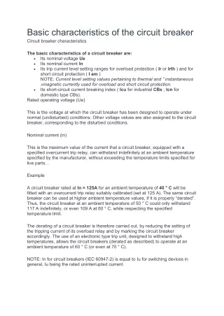
This is the voltage at which the circuit breaker has been designed to operate under normal (undisturbed) conditions. Other voltage values u200bu200bare also assigned to the circuit breaker, corresponding to the disturbed conditions.<br><br>

E N D
Basic characteristics of the circuit breaker Circuit breaker characteristics The basic characteristics of a circuit breaker are: •Its nominal voltage Ue •Its nominal current In •Its trip current level setting ranges for overload protection ( Ir or Irth ) and for short circuit protection ( I am ) NOTE: Current level setting values pertaining to thermal and ” instantaneous »magnetic currently used for overload and short circuit protection. •Its short-circuit current breaking index ( Icu for industrial CBs ; Icn for domestic type CBs). Rated operating voltage (Ue) This is the voltage at which the circuit breaker has been designed to operate under normal (undisturbed) conditions. Other voltage values are also assigned to the circuit breaker, corresponding to the disturbed conditions. Nominal current (in) This is the maximum value of the current that a circuit breaker, equipped with a specified overcurrent trip relay, can withstand indefinitely at an ambient temperature specified by the manufacturer, without exceeding the temperature limits specified for live parts. . Example A circuit breaker rated at In = 125A for an ambient temperature of 40 ° C will be fitted with an overcurrent trip relay suitably calibrated (set at 125 A). The same circuit breaker can be used at higher ambient temperature values, if it is properly “derated”. Thus, the circuit breaker at an ambient temperature of 50 ° C could only withstand 117 A indefinitely, or even 109 A at 60 ° C, while respecting the specified temperature limit. The derating of a circuit breaker is therefore carried out, by reducing the setting of the tripping current of its overload relay and by marking the circuit breaker accordingly. The use of an electronic type trip unit, designed to withstand high temperatures, allows the circuit breakers (derated as described) to operate at an ambient temperature of 60 ° C (or even at 70 ° C). NOTE: In for circuit breakers (IEC 60947-2) is equal to Iu for switching devices in general, Iu being the rated uninterrupted current.
Frame size classification A circuit breaker that can be fitted with overcurrent trip units with different current level adjustment ranges is assigned a rating that corresponds to the highest current level adjustment trip unit that can be fitted. Circuit-breaker Example UNE compact NSX630N The circuit breaker can be fitted with 11 electronic trip units from 150 A to 630 A. The size of the circuit breaker is 630 A. The setting of the overload relay tripping current ( Irth or Ir ) In addition to small circuit breakers which are very easily replaceable, industrial circuit breakers are equipped with removable overcurrent tripping relays, that is to say exchangeable. Additionally, in order to tailor a circuit breaker to the requirements of the circuit it controls and to avoid the need to run oversized cables, trip relays are
generally adjustable. The Ir or Irth trip current setting (both designations are in common use) is the current above which the circuit breaker will trip. It also represents the maximum current that the circuit breaker can withstand without tripping. This value must be greater than the maximum load current IB, but less than the maximum current allowed in the circuit. Iz . Thermal relays are generally adjustable from 0.7 to 1.0 times In, but when electronic devices are used for this purpose, the adjustment range is greater; typically 0.4 to 1 times In. UNE NSX630N circuit breaker equipped with a 400 A Micrologic 6.3E overcurrent trip relay, set to 0.9, will have a trip current setting: Ir = 400 x 0.9 = 360 A NOTE: For circuit breakers equipped with non-adjustable overcurrent tripping relays, Ir = In . Example: for the C60N 20 A circuit breaker, Ir = In = 20A . High Short circuit relay trip current setting ( I am ) Short-circuit tripping relays (instantaneous or slightly delayed) are intended to quickly trip the circuit breaker in the event of the occurrence of high values of fault current. Their I am trigger threshold is: •Either set by standards for domestic type household circuit breakers, eg. IEC 60898, or •Indicated by the manufacturer for industrial type circuit breakers according to associated standards, in particular IEC 60947-2. For these latter circuit breakers, there is a wide variety of tripping devices allowing the user to tailor the protection performance of the circuit breaker to the particular requirements of a load. (1) 50 In of IEC 60898, which most European manufacturers consider unrealistic – (Schneider Electric = 10 to 14 In). (2) For industrial use, IEC standards do not specify values. The above values are given only as those commonly used. • Ir: Adjustment of the overload relay tripping current (thermal or time delay) • I am: Adjustment of the tripping current of the short-circuit relay (magnetic or time delay) • Ii: Instant adjustment of the relay trip current by a short circuit. • Icu: breaking capacity Isolation function A circuit breaker is suitable for isolating a circuit if it meets all the conditions prescribed for a disconnector (at its rated voltage) in the corresponding standard. In such a case, it is called a circuit breaker-disconnector and is marked on its front face with the symbol. All Acti 9, Compact NSX and Masterpact LV switchboards from the Schneider Electric ranges fall into this category.
High Nominal short-circuit breaking capacity (Icu or Icn) A circuit breaker’s short-circuit current cutoff rate is the highest (potential) value of current that the circuit breaker is capable of breaking without being damaged. The current value quoted in the standards is the rms value of the AC component of the fault current, i.e. Transient DC component (which is always present in the worst possible case of short circuit) is assumed to be zero for the calculation of the normalized value. This nominal value ( Icu ) for industrial CBs and ( Icn ) for domestic type CBs is normally given in kA rms. Icu (ultimate breaking capacity denoted c.) And Ics (nominal breaking capacity in service) are defined in IEC 60947-2 with a table relating Ics with Icu for different categories of use A ( instantaneous tripping ) and B (timed tripping ). Tests aimed at proving the value noted sc The breaking capacities of circuit breakers are governed by standards and include: •Operating sequence comprising a succession of operations, namely closing and opening on short-circuit •Current and voltage phase shift. When the current is in phase with the supply voltage ( cos ϕ for the circuit = 1 ), interrupting the current is easier than this at any other power factor. Cutting a current at low heat insulation values of cos is considerably more difficult to achieve with a zero power factor circuit being (theoretically) the most expensive case. In practice, any short circuit fault in the power system currents are (plus or minus) at lagging power factors, and standards are based on values commonly considered representative of the majority of power systems. . In general, the higher the fault current level (at a given voltage), the lower the power factor of the fault current loop, for example near generators or large transformers. Figure 5 below extract from IEC 60947-2 relates the standardized values of cos to industrial circuit breakers according to their nominal value Icu . After an opening / closing time sequence to test the Icu capacity of a circuit breaker, additional tests are carried out to ensure that: •The dielectric withstand capacity •The performance of disconnection (isolation) and •The test did not alter the correct operation of the overload protection. There are other characteristics of a circuit-breaker not mentioned in this article: rated insulation voltage, rated impulse withstand voltage, rated short-time current, rated breaking capacity, rated breaking capacity and current limitation default