Download
1 / 22
220 likes | 498 Views
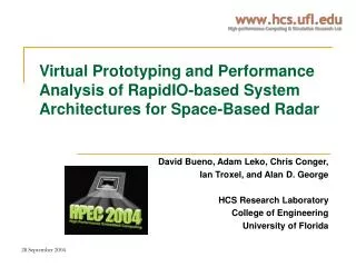
Virtual Prototyping and Performance Analysis of RapidIO-based System Architectures for Space-Based Radar. David Bueno, Adam Leko, Chris Conger, Ian Troxel, and Alan D. George HCS Research Laboratory College of Engineering University of Florida. Outline. Project Overview Background

E N D
Virtual Prototyping and Performance Analysis of RapidIO-based System Architectures for Space-Based Radar David Bueno, Adam Leko, Chris Conger, Ian Troxel, and Alan D. George HCS Research Laboratory College of Engineering University of Florida
Outline • Project Overview • Background • RapidIO (RIO) • Ground-Moving Target Indicator (GMTI) • Partitioning Methods • Modeling Environment and Models • Compute node and RIO endpoint models • RapidIO switch model • GMTI models • System and backplane model • Experiments and Results • Result latency • Switch memory utilization • Parallel efficiency • Conclusions
Project Overview • Simulative analysis of Space-Based Radar (SBR) systems using RapidIO interconnection networks • RapidIO (RIO) is a high-performance, switched interconnect for embedded systems • Can scale to many nodes • Provides better bisection bandwidth than existing bus-based technologies • Study optimal method of constructing scalable RIO-based systems for Ground Moving Target Indicator (GMTI) • Identify system-level tradeoffs in system designs • Discrete-event simulation of RapidIO network, processing elements, and GMTI algorithm • Identify limitations of RIO design for SBR • Determine effectiveness of various GMTI algorithm partitionings over RIO network Image courtesy [1]
Background- RapidIO • Three-layered, embedded system interconnect architecture • Logical – memory mapped I/O, message passing, and globally shared memory • Transport • Physical – serial and parallel • Point-to-point, packet-switched interconnect • Peak single-link throughput ranging from 2 to 64 Gb/s • Focus on 16-bit parallel LVDS RIO implementation for satellite systems Image courtesy [2]
Background- GMTI • GMTI used to track moving targets on ground • Estimated processing requirements range from 40 (aircraft) to 280 (satellite) GFLOPs • GMTI broken into four stages: • Pulse Compression (PC) • Doppler Processing (DP) • Space-Time Adaptive Processing (STAP) • Constant False-Alarm Rate detection (CFAR) • Incoming data organized as 3-D matrix (data cube) • Data reorganization (“corner turn”) necessary between stages for processing efficiency • Size of each cube dictated by Coherent Processing Interval (CPI)
GMTI Partitioning Methods- Straightforward • Data cubes divided among all Processing Elements (PEs) • Partitioned along optimal dimension for any particular stage • Data reorganization between stages implies personalized all-to-all communication (corner turn) stresses backplane links • Minimal latency • Entire cube must be processed within one CPI to receive next cube
GMTI Partitioning Methods- Staggered • Data cubes sent to groups of PEs in round-robin fashion • Limiting each Processing Group (PG) to a single board significantly reduces backplane bandwidth impact • Time given to each PG to receive and process a data cube is N × CPI • N = number of processing groups • CPI = amount of time between generated data cubes • Latency to produce result is higher than in straightforward partitioning
GMTI Partitioning Methods- Pipelined • Each PE group assigned to process a single stage of GMTI • Groups may have varying numbers of PEs depending upon processing requirements of each stage • Potential for high cross-system bandwidth requirements • Irregular and less predictable traffic distribution • Frequent communication between different group sizes • Latency to produce result is higher than straightforward method • One result emerges each CPI, but the results are three CPIs old
Model of Compute Node with RIO Endpoint Model Library Overview • Modeling library created using Mission Level Designer (MLD), a commercial discrete-event simulation modeling tool • C++-based, block-level, hierarchical modeling tool • Algorithm modeling accomplished via script-based processing • All processing nodes read from a global script file to determine when/where to send data, and when/how long to compute • Our model library includes: • RIO central-memory switch • Compute node with RIO endpoint • GMTI traffic source/sink • RIO logical message-passing layer • Transport and parallel physicallayers
Model of RIO Central-Memory Switch RapidIO Models • Key features of Endpoint model • Message-passing logical layer • Transport layer • Parallel physical layer • Transmitter- and receiver-controlled flow control • Error detection and recovery • Priority scheme for buffer management • Adjustable link speed and width • Adjustable priority thresholds and queue lengths • Key features of Central-memory switch model • Selectable cut-through or store-and-forward routing • High-fidelity TDM model for memory access • Adjustable priority thresholds based on free switch memory • Adjustable link rates, etc. similar to endpoint model
Model of Four-Processor Board Processor script send… receive… Simulation Script generator GMTI & system parameters GMTI Processor Board Models • System contains many processor boards connected via backplane • Each processor board contains one RIO switch and four processors • Processors modeled with three-stage finite state machine • Send data • Receive data • Compute • Behavior of processors controlledwith script files • Script generator converts high-levelGMTI parameters to script • Script is fed into simulations
System Design Constraints • 16-bit parallel 250MHz DDR RapidIO links (1 GB/s) • Expected radiation-hardened component performance by time RIO and SBR ready to fly in ~2008 to 2010 • Systems composed of processor boards interconnected by RIO backplane • 4 processors per board • 8 Floating-Point Units (FPUs) per processor • One 8-port central-memory switch per board; implies 4 connections to backplane per board • Baseline GMTI algorithm parameters: • Data cube: 64k ranges, 256 pulses, 6 beams • CPI = 256ms • Requires ~3 GB/s of aggregate throughput from source to sink to meet real-time constraints
7-Board System Backplane-to-Board 4, 5, 6, and Data Source Connections 4-Switch Non-blocking Backplane Backplane and System Models • High throughput requirements for data source and corner turns require non-blocking connectivity between all nodes and data sources Backplane-to-Board 0, 1, 2, 3 Connections
Overview of Experiments • Experiments conducted to evaluate strengths and weaknesses of each partitioning method • Same switch backplane used for each experiment • Varied data cube size • 256 pulses, 6 beams for all tests • Varied number of ranges from 32k to 64k • Several system sizes used • Analysis determined that 7-board configuration necessary for straightforward method to meet deadline • Both 6- and 7-board configurations used for pipelined method • Staggered method does not benefit from a system larger than 5 boards with configuration used • Staggering performed with one processor board per group • Larger system-configurations leave processors idle
Result Latency Comparison • Result latency is interval from data arrival until results reported • Straightforward achieved lowest latency, required most processor boards • No result for 64k ranges because system could not meet real-time deadline • Staggered requires least number of processor boards to meet deadline • Efficient system configuration, small communication groups • Tradeoff is result latency • Pipelined method a compromise
7-board, straightforward, 48k ranges Switch Memory Histogram with Straightforward Method • Chart shows frequency of time free switch memory lies in each bracket • Max switch memory is 16384 bytes • Results taken from switch on processor board 1 • All processor board switches see essentially identical memory usage • ~90% of time is spent with switch ~80% free • Most predictable communication patterns, enabling effective static planning of comm. paths
5-board, staggered, 48k ranges Switch Memory Histogram with Staggered Method • Staggered method uses slightly more memory over course of simulation • More data flows through single switch during corner turn • Less spread in communication patterns than straightforward method • More switch memory usage indicates more contention for a particular port, not necessarily more utilization or communication
7-board, pipelined, 48k ranges Switch Memory Histogram with Pipelined Method • Pipelined method stresses network • Irregular comm. patterns • Greater possibility for output port contention • Non-blocking network not helpful when multiple senders vying for same destination • Difficult to plan out optimal comm. paths beforehand • Much synchronization required to stagger many-to-one communication, but not extremely costly in total execution time
Average Parallel Efficiency • Parallel efficiency defined as sequential execution time (i.e. result latency) divided by N times the parallel execution time • N = number of processors that work on a single CPI • Pipelined efficiency a special case, must use N/3 for fair comparison (shown) since all processors do not work on a CPI at the same time • Staggered method most efficient due to small communication groups and low number of processors working on same CPI • Straightforward method worst for opposite reason, pipelined method a compromise
Conclusions • Developed suite of simulation models and mechanisms for evaluation of RapidIO designs for space-based radar • Evaluated three partitioning methods for GMTI over a fixed RapidIO non-blocking network topology • Straightforward partitioning method produced lowest result latencies, but least scalable • Unable to meet real-time deadline with our maximum data cube size • Staggered partitioning method produced worst result latencies, but highest parallel efficiency • Also able to perform algorithm with least number of processing boards • Important for systems where power consumption, weight are a concern • Pipelined partitioning method is a compromise in terms of latency, efficiency, and scalability, but heavily taxes network • RapidIO provides feasible path to flight for space-based radar • Future work to focus on additional SBR variants (e.g. Synthetic Aperture Radar) and experimental RIO analysis
Bibliography [1] http://www.afa.org/magazine/aug2002/0802radar.asp [2] G. Shippen, “RapidIO Technical Deep Dive 1: Architecture & Protocol,” Motorola Smart Network Developers Forum, 2003. [3] “RapidIO Interconnect Specification (Parts I-IV), ” RapidIO Trade Association, June 2002. [4] “RapidIO Interconnect Specification, Part VI: Physical Layer 1x/4x LP-Serial Specification,” RapidIO Trade Association, June 2002. [5] M. Linderman and R. Linderman, “Real-Time STAP Demonstration on an Embedded High Performance Computer,” Proc. of the IEEE National Radar Conference, Syracuse, NY, May 13-15, 1997. [6] “Space-Time Adaptive Processing for Airborne Radar,” Tech. Rep. 1015, MIT Lincoln Laboratory, 1994. [7] G. Schorcht, I. Troxel, K. Farhangian, P. Unger, D. Zinn, C. Mick, A. George, and H. Salzwedel, “System-Level Simulation Modeling with MLDesigner,” Proc. of 11th IEEE/ACM International Symposium on Modeling, Analysis, and Simulation of Computer and Telecommunications Systems (MASCOTS), Orlando, FL, October 12-15, 2003. [7] R. Brown and R. Linderman, “Algorithm Development for an Airborne Real-Time STAP Demonsttration,” Proc. of the IEEE National Radar Conference, Syracuse, NY, May 13-15, 1997. [8] A. Choudhary, W. Liao, D. Weiner, P. Varshney, R. Linderman, M. Linderman, and R. Brown, “Design, Implementation and Evaluation of Parallel Pipelined STAP on Parallel Computers,” IEEE Trans. on Aerospace and Electrical Systems, vol. 36, pp 528-548, April 2000.
Acknowledgements • We wish to thank Honeywell Space Systems in Clearwater, FL for their funding and technical guidance in support of this research. • We wish to thank MLDesign Technologies in Palo Alto, CA for providing us the MLD simulation tool that made this work possible.