Download
1 / 15
160 likes | 404 Views
Scoping Study of FLiBe Evaporation and Condensation. A. R. Raffray and M. Zaghloul University of California, San Diego ARIES-IFE Meeting General Atomics San Diego July 1-2, 2002. Outline. • FLiBe properties used in analysis - Vapor pressure as a function of temperature

E N D
Scoping Study of FLiBe Evaporation and Condensation A. R. Raffray and M. Zaghloul University of California, San Diego ARIES-IFE Meeting General Atomics San Diego July 1-2, 2002
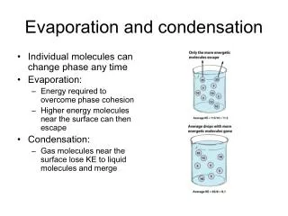
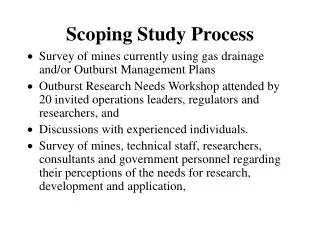
Outline • FLiBe properties used in analysis - Vapor pressure as a function of temperature - Other properties • Condensation rates and characteristic time for FLiBe • Aerosol source term - Photon energy deposition and explosive boiling - Estimate of amount of FLiBe expulsed from surface • End-goal: example parameter window plot
FLiBe Vapor Pressure • e-mail communications among UCSD, ORNL and Berkeley • From Olander’s calculated values: log10 (P(Torr)) = 9.55-11109.56/T(K); T= 773 K - 973 K • From ORNL’s measured values: log10 (P(Torr))=9.009-10444.11/T(k); T= 1223 K - 1554 K • Expression used for the analysis (fit from above two): - log10 (P(Torr))=9.3806-10965.26/T(K); T = 773 K - 1554 K
Physical Properties for Film Materials Property Pb FLiBe Li Tmelting (K) 600.5 732.2 452 Tboiling, 1 atm (K) 1893 1687 1590 Tcritical (K) 4836 4498.8 (* ) 3223 Density (kg/m3) 11291 – 1.1647 T 2413 - 0.488 T 519.73 – 0.01 T Log10 (Ptorr) = 7.91 - 9923/T Vapor Pressure Log10 (Ptorr) = 7.764 - 7877.9/T Log10 (Ptorr) = 9.38 - 10965.3/T CP (J/kg-K) 4227.57 - 0.0733 T 2347 =183.6 -0.07 T-1.6x10⁶ T-2+ 3.5x10⁻⁵ T2+ 5x10⁻⁹ T3 hfg (J/kg) = 46.61 - 0.003T +4.7710-7 T2 (=8.6x10⁶ at 1893 K) = 8.965106 - 2347T (* *) (= 5.3x10⁶ at 1687 K) = 4.9810-8T2 - 2.05 T + 38.01 All temperatures, T, in K (*) Xiang M. Chen, Virgil E. Schrock and Per F. Peterson, “The Soft-Sphere Equation of State for Liquid FLiBe,” Fusion Technology, Vol. 21, 1992. (**) Derived from Cp and the Cohesive energy @ 1atm.
jevap Pg Tg Tf jcond Condensation Flux and Characteristic Time to Clear Chamber as a Function of FLiBe Vapor and Film Conditions • Characteristic time to clear chamber, tchar, based on condensation rates and FLiBe inventory for given conditions • For ~0.1 s between shots Pvap prior to next shot could be up to ~10 x Psat • Not likely to be a major problem • Of more concern is aerosol generation and behavior • For higher Pvap (>0.1 Pa for assumed conditions), tchar is independent of • For lower Pvap as condensation slows down, tchar increases substantially
X-ray Spectra and Cold Opacities Used in Aerosol Source Term Estimate • X-ray spectra much softer for indirect drive target (90% of total energy associated with < 5 keV photons • Cold opacity calculated from cross section data available from LLNL (EPDL97)
Photon Energy Deposition in Vapor and Film • Example Vapor Pressure = 1 mTorr - Corresponding to TPb= 910 K; TFLiBe= 886 K; TLi= 732 K • For film, most of photon energy deposited: - within order of 1 mm for Pb film - within order of 10 mm for FLiBe film - important for aerosol source term • Photon energy deposited in vapor for R=6.5 m: - ~1% in Pb vapor - < 0.1% in FLiBe vapor
Energy Deposition & Transient Heat Transport x Induced Thermal- Spikes Fast Ions y z Mechanical Response Phase Transitions Slow Ions • Stresses and Strains and Hydrodynamic Motion • Fractures and Spall • Surface Vaporization • Heterogeneous Nucleation • Homogeneous Nucleation (Phase Explosion) Material Removal Processes Expansion, Cooling and Condensation Processes Leading to Aerosol Formation following High Energy Deposition Over Short Time Scale Surface Vaporization Liquid Film X-Rays Impulse Spall Fractures Impulse Phase Explosion Liquid/Vapor Mixture
Example results for Pb Ion-like heating rate Photon-like heating rate Vaporization from Free Surface • Occurs continuously at liquid surface • Governed by the Hertz-Knudsen equation for flux of atoms e = vaporization coefficient, c = condensation coefficient, m = mass of evaporating atom, k = Boltzmann’s constant, Ps = saturation pressure Pv = pressure of vapor Tf = film temperature Tv = vapor temperature • Liquid-vapor phase boundary recedes with velocity: • For constant heating rate, g, and expression for Ps =f(T), the following equation can be integrated to estimate fractional mass evaporated over the temperature rise. • Free surface vaporization is very high for heating rate corresponding to ion energy deposition • For much higher heating rate (photon-like) free surface vaporization does not have the time to occur and its effect is much reduced
Example results for Pb Photon-like heating rate Ion-like heating rate Vaporization into Heterogeneous Nuclei • Occurs at or somewhat above boiling temperature, T0 • Vapor phase appears at perturbations in the liquid (impurities etc.) • From Matynyuk, the mass vaporized into heterogeneous nuclei per unit time is given by: v = density of vapor in the nucleus, hfg = enthalpy of vaporization per unit mass, 0 = density of saturated vapor at normal boiling temperature (T0) P0 is the external static pressure • Heterogeneous nucleation is dependent on the number of nuclei per unit mass but is very low for heating rate corresponding to ion energy deposition and even lower for photon-like energy deposition • The equation can be integrated over temperature for a given heating rate, g, and following some simplifying assumptions (Fucke and Seydel).
; • A metastable liquid has an excess free energy, so it decomposes explosively into liquid and vapor phases. - As T/Ttc > 0.9, Becker-Döhring theory of nucleation indicates avalanche-like and explosive growth of nucleation rate (by 20-30 orders of magnitude) Phase Explosion (Explosive Boiling) • Rapid boiling involving homogeneous nucleation • High heating rate - Pvapor does not build up as fast and thus falls below Psat @ Tsurface - superheating to a metastable liquid state - limit of superheating is the limit of thermodynamic phase stability, the spinode (defined by P/v)T = 0) • A given metastable state can be achieved in two ways: - increasing T over BP while keeping P < Psat (e.g. high heating rate) - reducing P from Psat while keeping T >T sat (e.g. rarefaction wave)
Sensible energy based on uniform vapor pressure following photon passage in chamber and including evaporated FLiBe from film Cohesion energy (total evaporation energy) 0.9 Tcritical Sensible energy (energy to reach saturation) Explosive boiling region Evaporated thickness 2-phase region 5.52 3.7 12.24 Photon Energy Deposition Density Profile in FLiBe Film and Explosive Boiling Region Explosive boiling region as lower bound estimate for aerosol source term , ~5.52 mm for FLiBe
Pb vapor (1 mtorr 910 K) FLiBe vapor (1 mtorr 886 K) Li vapor (1 mtorr 732 K) Pvapor,interface / P0 2.44105 1.92105 6.07104 Cohesive energy, Et (GJ/m3) 9.14 10.07 11.51 0.15 0.18 9.0010-2 Vapor quality in the remaining 2-phase region dexplosive boil. (mm) 2.46 5.59 3.39 mexplosive boil. (kg) 12.89 4.27 0.85 mtot(kg) 13.91 5.08 1.21 Summary of Results for Different Film Materials under the Indirect Drive Photon Threat Spectra • Tsat estimated from Pvapor,interface initial vapor pressure (P0=1 mtorr) heated by photon passage plus additional pressure due to evaporation from film based on chamber volume • Adding the vapor component from the 2-phase region remaining after explosive boiling only slightly increases total expulsed mass (mtot vs. mexplosive,boil.) • mtot would be lower-bound source term for chamber aerosol analysis
Comparison of Simple Explosive Boiling Estimates with ABLATOR Results • ABLATOR graciously provided by LLNL • ABLATOR is an integrated code modeling energy deposition and armor thermal response including melting, evaporation, boiling and spalling • In the interest of time comparison done for a case already available in ABLATOR input file • Results for Al armor under given X-ray spectra and fluence 32.5 J/cm2 assuming a square pulse over 3 ns • Melting depth - ABLATOR: 10.6 mm - Simple volumetric model: 10.1 mm • Vaporization depth: - ABLATOR: 1.863 mm - Simple volumetric model: 2.25 mm • Explosive boiling depth: - ABLATOR (assumed as depth where nucleation rate > 1024 s-1): 4.32 mm - Simple volumetric model (T~ 0.9 Tcrit): 4.14 mm • Results from simple model reasonably close to ABLATOR results suggesting that the simple model could be used for scoping analysis
Example Aerosol Operating Parameter Window Tracking (only as example) ID: 580 mm DD: 0.05 mm • Use explosive boiling results as input for aerosol calculations • Perform aerosol analysis to obtain droplet concentration and sizes prior to next shot (NOT DONE YET) • Apply target and driver constraints (e.g. from R. Petzoldt) From P. Sharpe’s preliminary calculations for Pb 100 • Need aerosol analysis for explosive boiling source case for Pb and FLiBe • Need target tracking constraints for FLiBe • Need to finalize driver constraints on aerosol size and distribution