Download
1 / 7
70 likes | 109 Views
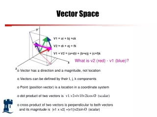
Matrix converters as induction motor drivers have received considerable attention in recent years because of its good alternative to voltage source inverter pulse width modulation (VSI-PWM) converters. This paper presents the work carried out in developing a mathematical model for a space vector modulated (SVM) direct controlled matrix converter. The mathematical expressions relating the input and output of the three phase matrix converter are implemented by using MATLAB/SIMULINK. The duty cycles of the switches are modeled using space vector modulation for 0.5 and 0.866 voltage transfer ratios. Simulations of the matrix converter loaded by passive RL load and active induction motor are performed. A unique feature of the proposed model is that it requires very less computation time and less memory compared to the power circuit realized by using actual switches. In addition, it offers better spectral performances, full control of the input power factor, fully utilization of input voltages, improve modulation performance and output voltage close to sinusoidal.

E N D
ELECTRICAL PROJECTS USING MATLAB/SIMULINK ELECTRICAL PROJECTS USING MATLAB/SIMULINK Gmail:asokatechnologies@gmail.com, Website: http://www.asokatechnologies.in 0-9347143789/9949240245 Analysis and Mathematical Modelling Of Space Vector Modulated Direct Controlled Matrix Converter ABSTRACT: Matrix converters as induction motor drivers have received considerable attention in recent years because of its good alternative to voltage source inverter pulse width modulation (VSI-PWM) converters. This paper presents the work carried out in developing a mathematical model for a space vector modulated (SVM) direct controlled matrix converter. The mathematical expressions relating the input and output of the three phase matrix converter are implemented by using MATLAB/SIMULINK. The duty cycles of the switches are modeled using space vector modulation for 0.5 and 0.866 voltage transfer ratios. Simulations of the matrix converter loaded by passive RL load and active induction motor are performed. A unique feature of the proposed model is that it requires very less computation time and less memory compared to the power circuit realized by using actual switches. In addition, it offers better spectral performances, full control of the input power factor, fully utilization of input voltages, improve modulation performance and output voltage close to sinusoidal. KEYWORDS: 1.Matrix Converter 2.Space Vector Modulation 3.Simulation Model 4. Induction Motor SOFTWARE: MATLAB/SIMULINK For Simulation Results of the project Contact Us Gmail:asokatechnologies@gmail.com, Website: http://www.asokatechnologies.in 0-9347143789/9949240245
ELECTRICAL PROJECTS USING MATLAB/SIMULINK ELECTRICAL PROJECTS USING MATLAB/SIMULINK Gmail:asokatechnologies@gmail.com, Website: http://www.asokatechnologies.in 0-9347143789/9949240245 BLOCK DIAGRAM: Figure 1: Block diagram of simulation model for direct matrix converter For Simulation Results of the project Contact Us Gmail:asokatechnologies@gmail.com, Website: http://www.asokatechnologies.in 0-9347143789/9949240245
ELECTRICAL PROJECTS USING MATLAB/SIMULINK ELECTRICAL PROJECTS USING MATLAB/SIMULINK Gmail:asokatechnologies@gmail.com, Website: http://www.asokatechnologies.in 0-9347143789/9949240245 EXPECTED SIMULATION RESULTS: Figure 2: Result for sector identification Figure 3: Input and output voltage with passive load for q=0.5; R=135.95Ω, L=168.15mH, Vim=100 V, fo= 60Hz, fs = 2kHz For Simulation Results of the project Contact Us Gmail:asokatechnologies@gmail.com, Website: http://www.asokatechnologies.in 0-9347143789/9949240245
ELECTRICAL PROJECTS USING MATLAB/SIMULINK ELECTRICAL PROJECTS USING MATLAB/SIMULINK Gmail:asokatechnologies@gmail.com, Website: http://www.asokatechnologies.in 0-9347143789/9949240245 Figure 4: Input and output voltage with passive load for q=0.866; R=135.95Ω, L=168.15mH, Vim=100 V, fo= 60Hz, fs= 2kHz Figure 5: Input and output voltage with loaded induction motor for q=0.5; 3hp, Rs=0.277Ω, Rr=0.183Ω, Nr=1766.9rpm, Lm=0.0538H, Lr=0.05606H, Ls=0.0533H, fo=60Hz, fs=2kHz For Simulation Results of the project Contact Us Gmail:asokatechnologies@gmail.com, Website: http://www.asokatechnologies.in 0-9347143789/9949240245
ELECTRICAL PROJECTS USING MATLAB/SIMULINK ELECTRICAL PROJECTS USING MATLAB/SIMULINK Gmail:asokatechnologies@gmail.com, Website: http://www.asokatechnologies.in 0-9347143789/9949240245 Figure 6: Input and output voltage with loaded induction motor for q=0.866; 3hp, Rs=0.277Ω, Rr=0.183Ω, Nr=1766.9rpm, Lm=0.0538H, Lr=0.05606H, Ls=0.0533H, fo=60Hz, fs=2kHz Figure 7: Input current with passive load; R=135.95Ω,L=168.15mH, Vim=100 V, fo= 60Hz, fs= 2kHz (a) q=0.5, (b) q = 0.866 For Simulation Results of the project Contact Us Gmail:asokatechnologies@gmail.com, Website: http://www.asokatechnologies.in 0-9347143789/9949240245
ELECTRICAL PROJECTS USING MATLAB/SIMULINK ELECTRICAL PROJECTS USING MATLAB/SIMULINK Gmail:asokatechnologies@gmail.com, Website: http://www.asokatechnologies.in 0-9347143789/9949240245 Figure 8: Input current with loaded induction motor for q=0.866; 3hp, Rs =0.277Ω, Rr=0.183Ω, Nr=1766.9rpm, Lm=0.0538H, Lr=0.05606H, Ls=0.0533H, fo=60Hz, fs=2kHz CONCLUSION: The main constraint in the theoretical study of matrix converter control is the computation time it takes for the simulation. This constraint has been overcome by the mathematical model that resembles the operation of power conversion stage of matrix converter. This makes the future research on matrix converter easy and prosperous. The operation of direct control matrix converter was analysed using mathematical model with induction motor load for 0.866 voltage transfer ratio. For Simulation Results of the project Contact Us Gmail:asokatechnologies@gmail.com, Website: http://www.asokatechnologies.in 0-9347143789/9949240245
ELECTRICAL PROJECTS USING MATLAB/SIMULINK ELECTRICAL PROJECTS USING MATLAB/SIMULINK Gmail:asokatechnologies@gmail.com, Website: http://www.asokatechnologies.in 0-9347143789/9949240245 REFERENCES: [1]. A. Alesina, M.G.B.V., Analysis And Design Of Optimum-Amplitude Nine – Switch Direct AC-AC Converters. IEEE Trans. On Power. Electronic, 1989. 4. [2]. D. Casadei, G.S., A. Tani, L. Zari, Matrix Converters Modulation Strategies : A New General Approach Based On Space-Vector Representation Of The Switch State. IEEE Trans. On Industrial Electronic, 2002. 49(2). [3]. P. W. Wheeler, J.R., J. C. Claire, L. Empringham, A. Weinstein, Matrix Converters : A Technology Review. IEEE Trans. On Industrial Electronic, 2002. 49(2). [4]. H. Hara, E.Y., M. Zenke, J.K. Kang, T. Kume. An Improvement Of Output Voltage Control Performance For Low Voltage Region Of Matrix Converter. In Proc 2004 Japan Industry Applications Society Conference, No. 1-48, 2004. (In Japanese). 2004 [5]. Ito J, S.I., Ohgushi H, Sato K, Odaka A, Eguchi N., A Control Method For Matrix Converter Based On Virtual Ac/Dc/Ac Conversion Using Carrier ComparisonMethod. Trans Iee Japan Ia 2004. 124-D: P. 457–463. For Simulation Results of the project Contact Us Gmail:asokatechnologies@gmail.com, Website: http://www.asokatechnologies.in 0-9347143789/9949240245