Download
1 / 5
50 likes | 118 Views
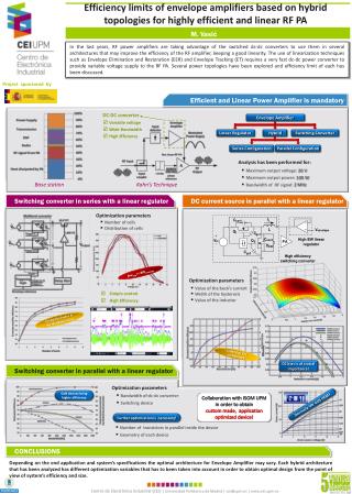
Smart grid applications, renewable energy utilization and electric vehicles (EVs) are attracting researchers due to their importance nowadays as well as in the future. An efficient power electronic converter is a main and common topic for research in this area. In this paper, a prototype of the electrical part of a power-train for EVs using an advanced multilevel converter topology is introduced, discussed and analysed. A comparison between the advanced converter, two-level and conventional multilevel converter topology is discussed as well. A switch function model is derived and discussed for the proposed converter. A mathematical model for the converter supplied by a fuel-cell (FC) and boost-converter (BC) is implemented with Matlab/Simulink. The simulation results are analysed to evaluate the converter. The evaluation is based on the harmonic analysis and power loss calculations. The converters are tested at different switching frequencies to show the effect of this variable on the converter loss. The results indicate that the proposed converter is 1.32% more efficient compared to conventional five-level DCC. Moreover, the lowest harmonic content, for all of the studied converters, is the proposed one

E N D
ELECTRICAL PROJECTS USING MATLAB/SIMULINK ELECTRICAL PROJECTS USING MATLAB/SIMULINK Gmail:asokatechnologies@gmail.com, Website: http://www.asokatechnologies.in 0-9347143789/9949240245 An Advanced Multilevel Converter Topology with Reduced Switching Elements ABSTRACT: Smart grid applications, renewable energy utilization and electric vehicles (EVs) are attracting researchers due to their importance nowadays as well as in the future. An efficient power electronic converter is a main and common topic for research in this area. In this paper, a prototype of the electrical part of a power-train for EVs using an advanced multilevel converter topology is introduced, discussed and analysed. A comparison between the advanced converter, two-level and conventional multilevel converter topology is discussed as well. A switch function model is derived and discussed for the proposed converter. A mathematical model for the converter supplied by a fuel-cell (FC) and boost-converter (BC) is implemented with Matlab/Simulink. The simulation results are analysed to evaluate the converter. The evaluation is based on the harmonic analysis and power loss calculations. The converters are tested at different switching frequencies to show the effect of this variable on the converter loss. The results indicate that the proposed converter is 1.32% more efficient compared to conventional five- level DCC. Moreover, the lowest harmonic content, for all of the studied converters, is the proposed one KEYWORDS: 1.Multilevel converter, 2.Diode-clamped-Converter, 3.T5 converter SOFTWARE: MATLAB/SIMULINK For Simulation Results of the project Contact Us Gmail:asokatechnologies@gmail.com, Website: http://www.asokatechnologies.in 0-9347143789/9949240245
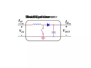
ELECTRICAL PROJECTS USING MATLAB/SIMULINK ELECTRICAL PROJECTS USING MATLAB/SIMULINK Gmail:asokatechnologies@gmail.com, Website: http://www.asokatechnologies.in 0-9347143789/9949240245 BLOCK DIAGRAM: Fig. 1. Block diagram for the proposed system as a part of EVs prototype. SIMULINK BLOCK DIAGRAM: Fig. 2. Simulink block-diagram for the modulation function of the PD-SVPWM For Simulation Results of the project Contact Us Gmail:asokatechnologies@gmail.com, Website: http://www.asokatechnologies.in 0-9347143789/9949240245
ELECTRICAL PROJECTS USING MATLAB/SIMULINK ELECTRICAL PROJECTS USING MATLAB/SIMULINK Gmail:asokatechnologies@gmail.com, Website: http://www.asokatechnologies.in 0-9347143789/9949240245 EXPECTED SIMULATION RESULTS: Fig. 3. Controlled dc-link voltage Fig. 9. Phase-A voltage and current at a switching frequency of 5kHz Fig. 10. Machine speed and torque at full load operation Fig. 11. THD factor for two-level, T-type and converters For Simulation Results of the project Contact Us Gmail:asokatechnologies@gmail.com, Website: http://www.asokatechnologies.in 0-9347143789/9949240245
ELECTRICAL PROJECTS USING MATLAB/SIMULINK ELECTRICAL PROJECTS USING MATLAB/SIMULINK Gmail:asokatechnologies@gmail.com, Website: http://www.asokatechnologies.in 0-9347143789/9949240245 CONCLUSION: A prototype for an EV using an advanced multilevel converter is introduced, analysed, and discussed. A switching function model for the T5 is derived, discussed and built on Matlab/Simulink. The converter is loaded by an induction machine as a part of the EV system. The comparison between the proposed converter and conventional DCC converter indicates that the proposed one has lower switching elements, reduced converter loss, simplified power circuit, driving as well as control circuits. The harmonic analysis indicated that the proposed converter has the lowest THD factor for both voltage and current compared to two as well as three-level converters. The power loss calculation indicates that the proposed converter increases the efficiency of the five-level converter by 1.32%. The T-type converter has lower losses but with more harmonic contents which affects the machine losses. The study indicatesthat the proposed converter is efficient to be used for ac drive,electric vehicles and renewable energy applications REFERENCES: [1] Majid Zandi, Alireza Payman, Jean-Philippe Martin, Serge Pierfederici, Bernard Davat, ”Energy Management of a Fuel Cell/Supercapacitor/Battery Power Source for Electric Vehicular Applications,” IEEE Trans. of Vehicular Technology, vol. 60, no. 2, Feb. 2011. [2] Alireza Payman, Serge Pierfederici, and Farid Meibody, ” Energy Management in a Fuel Cell/Supercapacitor Multisource/Multiload Electrical Hybrid System,” IEEE Trans. of Power Electronics, vol. 24, no. 12, December 2009. [3] Omar Z.Sharaf, Mehmet F. Orhan, ” An overview of fuel cell technology: Fundamentals and applications,” Renewable and Sustainable EnergyReviews, vol. 32 , pp. 810 - 853, 2014. [4] M. Al Sakka, J. Van Mierlo, H. Gualous, and P. Lataire,” Comparison of 30KWDC/DC Converter topologies interfaces for fuel cell in hybrid electric vehicle,” 13th Eur. Conf. Power Electron. Appl., Barcelona, Spain , 8 - 10 Sep. 2009. For Simulation Results of the project Contact Us Gmail:asokatechnologies@gmail.com, Website: http://www.asokatechnologies.in 0-9347143789/9949240245
ELECTRICAL PROJECTS USING MATLAB/SIMULINK ELECTRICAL PROJECTS USING MATLAB/SIMULINK Gmail:asokatechnologies@gmail.com, Website: http://www.asokatechnologies.in 0-9347143789/9949240245 [5] Mubashwar Md., Mekhilef S., Mahrous A.,” Three-phase hybrid multilevel inverter with less power electronic components using space vector,”IET Power Electron., vol. 7, no. 5, pp. 1256 - 1265, 2014. For Simulation Results of the project Contact Us Gmail:asokatechnologies@gmail.com, Website: http://www.asokatechnologies.in 0-9347143789/9949240245