Download
1 / 16
170 likes | 401 Views
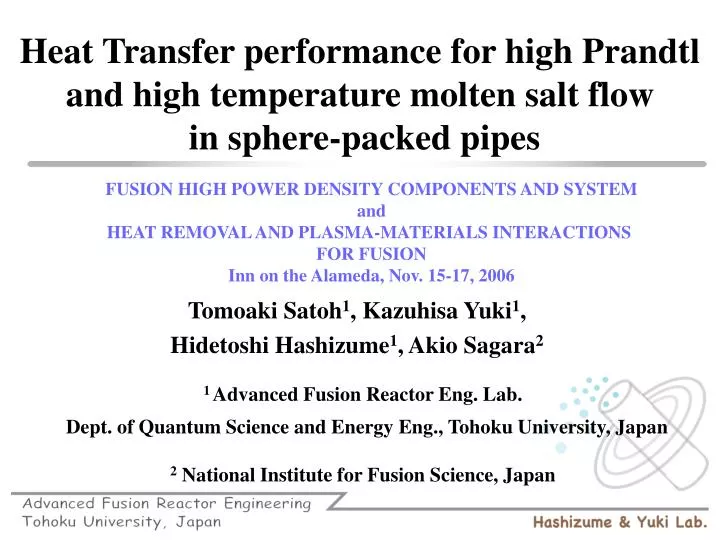
FUSION HIGH POWER DENSITY COMPONENTS AND SYSTEM and HEAT REMOVAL AND PLASMA-MATERIALS INTERACTIONS FOR FUSION Inn on the Alameda, Nov. 15-17, 2006. Heat Transfer performance for high Prandtl and high temperature molten salt flow in sphere-packed pipes. Tomoaki Satoh 1 , Kazuhisa Yuki 1 ,

E N D
FUSION HIGH POWER DENSITY COMPONENTS AND SYSTEM and HEAT REMOVAL AND PLASMA-MATERIALS INTERACTIONS FOR FUSION Inn on the Alameda, Nov. 15-17, 2006 Heat Transfer performance for high Prandtl and high temperature molten salt flow in sphere-packed pipes Tomoaki Satoh1, Kazuhisa Yuki1, Hidetoshi Hashizume1, Akio Sagara2 1 Advanced Fusion Reactor Eng. Lab. Dept. of Quantum Science and Energy Eng.,Tohoku University, Japan 2 National Institute for Fusion Science, Japan
1. Background1-1. Fusion blanket D-T Fusion Reaction D(2H)+T(3H) →4He + n + 17.06MeV Roles of a blanket in a fusion reactor • Generating and transporting heat energy • Shielding nuclear radiation • Producing and recovering Tritium Fig. 1. 3D view of FFHR In the design of a force-free helical reactor (FFHR), molten salt Flibe (LiF : BeF2 = 66 : 34) is recommended as a blanket material..
1. Background1-2. Flibe blanket system Advantages • MHD pressure drop is low in comparison with Li flow. • Stable in high temperature and vapor pressure is low, etc. Disadvantages • High Prandtl number fluid ⇒ Heat transfer performance is low • Electrolysis can occur due to induced current It is necessary to enhance heat transfer performance with relatively low flow velocity. To investigate heat transfer performance of Flibe, Tohoku-NIFS Thermofluid loop (TNT loop) was built in 1998.
Air cooler Circulation pump Dump Tank Flibe HTS Test section Fig. 1 Tohoku-NIFS Thermofluid loop (Before modification) Fig.2 Temperature dependance of Pr 1. Background1-3. Features of HTS Flibe contains toxic Be ⇒ Using alternative molten salt, HTS Comparison of features between Flibe and HTS Flibe (LiF - BeF2 : 66 - 34) Melting point : 459 C Pr : 35.6 @500 C Difficult to treat HTS (KNO3,NaNO2,NaNO3 : 53-40-7) Melting point : 142 C Pr :27.7 @200C No toxic substances
Fig. 4 Comparison between Re and Nu Causes of disagreements • Entrance region was too short to develop turbulence flow. • Heating method was not suitable for heat transfer experiment. 1. Background1-4. Early studies 450 mm Fig. 3 Overview of previous test section
1. Background1-5. Aim of this study TNT loop was modified. Entrance region : nearly 50D Direct electrical heating method Fig. 5 Tohoku-NIFS Thermofluid loop (After modification) Aim of this study • To investigate heat-transfer performance in a circular pipe using modified TNT loop, and to get more accurate data. • To quantitatively evaluate heat transfer enhancement of SPP by comparing with the performances of other heat transfer promoter.
Fig. 5 Tohoku-NIFS Thermofluid loop (After modification) 2. Experimental2-1. Experimental apparatus Air cooler Pump Dump tank Test section
2. Experimental2-1. Experimental apparatus 450mm About 1800mm (b) Modified test section (a) Previous test section Fig. 6 Comparison between modified test section and previous test section
Inner tube diameter:D=19mm Material:SUS304 T.C. for measuring inlet bulk temp. T.C. for measuring outlet bulk temp. Test section: About 50D Entrance region : 30D Flow straightener Stainless mesh Electrodes Flexible tubes 1000mm 1000mm To alleviate an effect of thermal stress 2. Experimental2-1. Experimental apparatus Length to develop boundary layer : lv lv = 0.693 × Re0.25 × D ( Re : Reynolds number, D : Inner tube diameter ) When Re = 15000, lv= 0.693 × 150000.25 × D ≈ 8D<< Entrance region Fig.7Schematic view of the modified section
3. Results and Discussion3-1. Chemical effect (a) Inlet (b) Center (c) Outlet Fig. 8 Observations of test-section inner surfaces HTS is thermally decomposed above 450C. Main reaction is as follows, The present study is carried out under the condition of HTS temperature up to 350C. ⇒ No chemical deposition No effect for heat transfer experiment.
Transition Entrance 3. Results and Discussion3-2. Heat transfer of circular pipe (CP) Developed Tin=200 [°C], Pr ≈ 27 Re=4610 q’’=30.6 [kW/m2] Thermal boundary layer is fully developed from 500 mm position. Temperatures measured in this region are used for evaluating heat transfer performance. Fig. 9 Typical temperature profile along the test section
3. Results and Discussion3-2. Heat transfer of circular pipe (CP) Modified Hausen equation (3500≤Re≤10000) Sieder-Tate equation (10000≤Re) Fig. 10 Comparison between acquired Nu and the empirical Eqs. Good agreement with above Eqs. Maximum error : 10%
3. Results and Discussion3-2. Heat transfer of circular pipe (CP) Modified Petukhov equation (104 ≤ Re ≤ 5x10⁶, 0.5 ≤ Pr ≤ 2000) Also good agreement with above Eq. Maximum error : 15% Fig. 11 Comparison between acquired heat transfer coefficient and the modified Petukhov Eq. Conclusion Heat transfer correlations for general fluid in CP can be used to evaluate heat transfer characteristics for high temp. molten salt.
3. Results and Discussion3-2. Heat transfer of sphere-packed pipes (SPP) Manglik equation for swerl tube 4 times higher Fand equation for SPP m = 0.25, n = 1, p = 0.4054, q = 0.5260, r = -0.6511. • SPP performance is higher than that of other heat transfer promoter. • It significant, especially, at low flow velocity condition. Fig. 12 Results of the heat transfer with packed bed under same velocity condition.
3. Results and Discussion3-2. Heat transfer of sphere-packed pipes (SPP) In the case of using D/2 spheres, pressure drop gives good agreements with drag model. (by M. OKUMURA et. al) Evaluating pumping power of SPP Fig. 12 Results of the heat transfer with packed bed under same pumping power.
Is there any future for Flibe ? Allowable temperature of structural material • =500C -> No solution • =550C -> Outlet temp. can be raised to 650C. Other coolant is necessary for first wall cooling. (or should we change the composition of Flibe to decrease melting temperature ?) • =650C -> Some possibility