Download
1 / 20
240 likes | 417 Views
US/Japan Workshop on Power Plant Studies and Related Advanced Technologies with EU Participation, April 6-7, 2002 (San Diego, CA). Estimation of Tritium Recovery from a Molten Salt Blanket of FFHR. Dept. Applied Quantum Physics and Nuclear Engineering, Kyushu University Satoshi FUKADA.

E N D
US/Japan Workshop on Power Plant Studies and Related Advanced Technologies with EU Participation, April 6-7, 2002 (San Diego, CA) Estimation of Tritium Recoveryfrom a Molten Salt Blanket of FFHR Dept. Applied Quantum Physics and Nuclear Engineering, Kyushu University Satoshi FUKADA
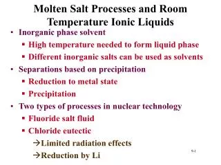
1. Background study :Characteristics of Flibe as a self-cooled blanket • Advantages (1) liquid blanket, low reactivity with air or water (2) low MHD effect (3) TBR >1 with addition of Be and low tritium solubility FFHR or HYLIFE-II • Disadvantages (1) less Flibe-facing structural materials under neutron irradiation (2) unknown tritium behavior or recovery in Flibe is not studied. (3) possibly high tritium leak to the environment (4) issues of Be safety JUPITER-II Relating to this study
Design activities in NIFS Collaboration Now, on going cf. NIFS annual repo.
1. Background study : Tritium recovery from Flibe relating to the things (1) Physical Properties (Underlined properties are not available or not reliable) • Tritium solubility (TF or T2) • Tritium diffusivity , permeation coefficient or mass-transfer coefficient • Viscosity, thermal diffusivity or heat-transfer coefficient • Phase diagram, vapor pressure, free energy change of fluoride formation Estimated from H2, D2 or other data (2) Affecting factors • Chemical forms of tritium in Flibe , T2, TF or T2O, or Flibe purification • REDOX control condition, change from TF to T2 • Corrosive HF or TF in Flibe • Isotopic effect and coexistent components to usepurified Flibe and REDOX control by Be
1. Background study : Necessary conditions imposed on apparatus of tritium recovery from Flibe • All tritium generated in a blanket is recovered • Very low tritium leak to the environment • Simple apparatus and easy to operate • Operation over melting temperature • High operation safety and material compatible with HF M+nHF⇨MFn+(n/2)H2 • Operated under low water vapor condition BeF2+2H2O≠Be(OH)2+2HF, LiF+H2O≠LiOH+HF Permeation window, He-Flibe counter-current column, Vacuum disengager
2. Design study : Design of tritium-recovery apparatus for FFHR Table 1 FFHR parameters on tritium recovery Assumptions • Based on FFHR design • Steady-state operation • Tritium generated in a blanket is transferred by Flibe and is recovered by a tritium recovery apparatus. • No isotope effect in properties • No decomposition of Flibe by VxB • We focused on whether or not tritium can be recovered by a realistic scale of apparatus. What is the rate-determining step of tritium recovery
2. Design study : Flow of Flibe and tritium Tritium generation rate (1 GWt) 190 g-T/day = 1.8 MCi/day Flibe blanket xin ( = KHpin or = KSpin0.5 ) Tritium leak rate 〜 KpAinpin0.5 570C Bypass ratio a Tritium recovery system Tritium recovery system 470C Be pebbles pump Tritium storage Tritium permeation barrier Flibe flow rate 2.3m3/s xout ( = KHpout or = KSpout0.5 ) Tritium leak rate 〜 KpAoutpout0.5 Tritium permeation barrier Heat exchanger Tritium leak rate to the environment 〜10 Ci/day KpAinpin0.5 + KpAoutpout0.5 + others
2. Design study : Evaluation of tritium leak • If there is no barrier for tritium leak, Qleak= 2x10⁻³mol-T/s = 5 MCi/day huge tritium leak (A=102m2, pT2=103Pa, Kp=3.15x10⁻¹¹mol/msPa0.5 (ferrite) , t=5mm) impossible to lower the tritium leak rate, < 10-8 Pa • If the heat exchanger or the tritium recovery system is surrounded by a stagnant Flibe (or Flinak) layer (barrier), Qleak= 6x10⁻¹⁰mol-T/s = 1.6Ci/day allowable tritium leak (A=102m2, pT2=103Pa, DT=5x10⁻⁹m2/s, KH=3.2x10⁻⁷mol/m3Pa, t=50cm ) • Other reliable tritium barrier with a factor of 106 is OK, if available (e.g. alumina)
2. Design study : Material balance of tritium in Flibe Necessary conditions QT=1.8MCi/day Qleak<10Ci/day Design of economic apparatus allowable a=0.1 is possible if 50cm shield is present Fig. 2 Relation between cin and cout
Permeation window He out Tritium getter Permeation material Flibe in Tritium permeation Flibe out Tritium permeation barrier (stagnant Flibe) He in Fig. 3 Permeation window system
2. Design study : Tritium transfer process in Flibe-facing material Processes include (1) Tritium (TF or T2) generation rate in Flibe (2) Tritium (TF or T2) diffusion in Flibe (3) Tritium (TF or T2) solution in Flibe (4) Tritium migration from Flibe surface to metal surface (impurity layer) (5)Tritium (T) permeation through metal (6)Desorption or absorption of tritium (TF or T2) from Flibe (7) Tritium (TF or T2) diffusion in gas (8) Tritium recombination on metal surface ( ) unique to Flibe Fig. 4 Mass transfer processes from Flibe to gas phase
2. Design study : Rate-determining step of permeation window Fig. 5 Rate-determining step of the overall tritium permeation clean Fluid Flibe film Impurity migration Permeation dirty
2. Design study :Design equations of permeation window • Permeation material : Ni, or ferritic steel • Upstream side : (purified) Flibe • Downstream side : He purge • Overall resistance of mass-transfer of tritium permeation • Tritium generated in blanket, QT, is all recovered by permeation window. 2.3m3/s Diffusion in Flibe Permeation through wall Fig. 5 Permeation window tritium recovery system
2. Design study :Estimation of permeation window area Tritium leak • Tritium recovery is easy at high tritium pressure (concentration) ⇨high tritium leak • Tritium recovery is difficult at low tritium pressure (concentration) ⇨large apparatus • Operation at around xT=0.2 ppm satisfies 10Ci/day limit and 190g/day recovery • Resistances of Flibe-film diffusion is controlling and permeation gives a small effect Large apparatus Fig. 6 Permeation window area (a=1, t=1mm)
Counter-current extraction tower Perforated plate Flibe in Raschig ring packing He out Tritium getter Downward Flibe flow Upward He flow Flibe out He in Tritium permeation barrier (stagnant Flibe) Fig. 8 Flibe-He counter-current extraction tower
2. Design study :Design equations for He extraction tower • Material balance equation • Gas-phase height transfer unit • Flibe-phase height transfer unit • Concentration profile (Solution) Fig. 9 Concentration change in extraction tower Rate-determining step is liquid phase diffusion.
2. Design study :Tritium concentration in He extraction tower • Tritium concentration in He almost increases logarithmically. • Tritium concentration in Flibe almost decreases logarithmically. • 105 of DF for Flibe-tritium system is possible by 5 m extraction tower. • 190 g/day tritium can be recovered by one extraction tower. • Values of HL are unsure because they are not determined by Flibe experiment but by water-hydrogen system. • (HTU)L >> (HTU)G Fig. 10 Tritium concentration in He extraction tower (a=0.1)
2. Design study : Analysis of vacuum disengager Assumptions • Flibe drops free fall from the top and dissolved tritium is desorbed by a vacuum pump. • dp=2mm, h=10m, a=0.1 • Surface recombination resistance is ignored. • Drop formation energy 〜1.4kW • Pumping power for perforation 〜 160kW Fig.11 Concentration profile in disengager
2. Design study : Conclusions from design study • Need a tritium barrier to control tritium leak below 10Ci/day • As long as the tritium leak rate is lower than the permissible level (e.g. by stagnant Flibe), arranging the tritium recovery system in a by-pass line is effective. • In that case, the recovery systems of the permeation window, extraction column and vacuum disengager are a realistic-scale apparatus. • Diffusion in fluid Flibe is the rate-determining step in the permeation window and He-Flibe counter-current column. • In order to raise the accuracy of the design, the mass-transfer coefficient from Flibe to extraction gas should be clearly determined.
2. Design study :On Flinabe as a blanket material (LiF-NaF-BeF2) advantages • Low melting point (=240C?), low operation temperature • TBR>1 may be possible with addition of Be. • Other physical properties may be similar to Flibe disadvantages • Activation of Na (formation of 22Na or 24Na) • There are no data available on tritium mass-transport More data are necessary for the design of the tritium recovery system