Download
1 / 39
630 likes | 2.22k Views
EEE381B Aerospace Systems & Avionics Radar Part 2 – The radar range equation Ref: Moir & Seabridge 2006, Chapter 3,4 Dr Ron Smith Outline Basic radar range equation Developing the radar range equation Design impacts Receiver sensitivity Radar cross-section Low observability Exercises

E N D
EEE381BAerospace Systems & Avionics Radar Part 2 – The radar range equation Ref: Moir & Seabridge 2006, Chapter 3,4 Dr Ron Smith
Outline • Basic radar range equation • Developing the radar range equation • Design impacts • Receiver sensitivity • Radar cross-section • Low observability • Exercises EEE381B
1. Basic radar range equation • There are many different versions of the radar range equation. • We will use, and fully derive, the one presented below. EEE381B
1.1 Components of the equation • Rmax – the maximum range of the radar • Pt – average power of the transmitter • G – gain of the transmit/receive antenna • λ – wavelength of the operating frequency • – radar cross-section of the target • Smin – minimum detectable signal power EEE381B
1.2 Units of the equation EEE381B
2.1 Transmitted power • Recall from the previous lecture that the average transmitted power is a function of peak pulse power and the pulse duration: EEE381B
2.2 Power density at target [4] • Recall that power density decreases as a function of distance traveled: EEE381B
2.3 Reflected power • The amount of power reflected back from a target is a function of the power density at the target and the target’s radar cross-section, : EEE381B
2.4 Power density of echo at antenna • The power density of the returned signal, echo, again spreads as it travels back towards the radar receive antenna. EEE381B
2.5 Power of echo at receiver* • The antenna captures only a portion of the echoed power density as a function of the receive antenna’s effective aperture: * In this equation the receiver is assumed to be all radar receive chain components except the antenna. EEE381B
2.6 Minimum detectable signal power • Therefore a radar system is capable of detecting targets as long as the received echo power is greater than or equal to the minimum detectable signal power of the receive chain: EEE381B
3. Radar design impacts • A careful study of the radar range equation provides further insight as to the effect of several radar design decisions. • In general the equation tells us that for a radar to have a long range, the transmitter must be high power, the antenna must be large and have high gain, and the receiver must be very sensitive. EEE381B
3.1 Power, Pt • Increases in transmitter power yield a surprisingly small increase in radar range, since range increases by the inverse fourth power. • For example, a doubling of transmitter peak power results increases radar range by only 19%, EEE381B
3.2 Time-on-target, /Tp • The average power transmitted can also be increased by increasing the pulse duty cycle, sometimes referred to as the “time-on-target”. • A combined doubling of the pulse width and doubling of the transmitter peak power will give a fourfold increase in average transmitted power, and ~41% increase in radar range. EEE381B
3.3 Gain, G • Antenna gain is a major consideration in the design of the radar system. • For a parabolic dish, doubling the antenna size (diameter) will yield a fourfold increase in gain and a doubling of radar range. EEE381B
3.4 Receiver sensitivity, Smin • Similar to that of transmitter power, increases in receiver sensitivity yield relatively small increases in radar range. • Only 19% range increase for a halving of sensitivity, and at the expense of false alarms. • Receiver design is a complex subject beyond the scope of this course, see §3.5.3. • Simplistically, the smaller the radar pulse width, the larger the required receiver bandwidth and the larger the receiver noise floor. EEE381B
3.4.1 Receiver bandwidth EEE381B
3.4.2 Signal-to-noise EEE381B
3.4.3 Receiver threshold EEE381B
4. Radar cross-section, • The radar cross-section of a target is a measure of its size as seen by a radar, expressed as an area, m2. • It is a complex function of the geometric cross-section of the target at the incident angle of the radar signal, as well as the directivity and reflectivity of the target. • The RCS is a characteristic of the target, not the radar. EEE381B
4.1.1 RCS of a metal plate • Large RCS, but decreases rapidly as the incident angle deviates from the normal. EEE381B
4.1.2 RCS of a metal sphere • Small RCS, but is independent of incident angle. EEE381B
4.1.3 RCS of a metal cylinder • RCS can be quite small or fairly large depending on orientation. EEE381B
The RCS of a trihedral (corner) is both large and relatively independent of incident angle. 4.1.4 RCS of a trihedral corner reflector EEE381B
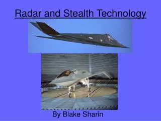
5. Low Observability • From the previous discussion on the radar cross-section of targets, it should be obvious that determining the radar cross-section of an airplane is a complicated task. • The art of designing an aircraft to specifically have a low RCS is known as low observability, or more commonly known as “stealth”. • Stealth is a relatively new technology, • even full RCS prediction is only 2 decades old. EEE381B
5.2 Aircraft high RCS areas [1] EEE381B
5.4 Comparative RCS [1] EEE381B
6. In-class exercises EEE381B
6.1 Quick response exercise # 1 • Think carefully about the derivation of the radar range equation just presented. Is there a potentially significant loss component missing? • Hint: recall the simple link equation from your very early lectures. EEE381B
6.2 Quick response exercise # 2 • Why have designers of stealth aircraft sought to blend the physical transitions / features of the aircraft? • Will reduction in your aircraft RCS alone make you invisible to the enemy? • How else might they find you? EEE381B
6.3 Radar range equation calculation • The US Navy AN/SPS-48 Air Search Radar is a medium-range, three-dimensional (height, range, and bearing) air search radar. • Published technical specifications include: • Operating frequency 2900-3100 MHz • Transmitter peak power 60-2200 kW • PRF 161-1366 Hz, and pulse widths of 9 / 3 μsec • Phased array antenna with a gain of 38.5 dB • For its published maximum range of 250 miles for a nominal target such as the F-18, what is the receiver chain sensitivity in bBm? EEE381B
References • Moir & Seabridge, Military Avionics Systems, American Institute of Aeronautics & Astronautics, 2006. [Sections 2.6 & 2.7] • David Adamy, EW101 - A First Course in Electronic Warfare, Artech House, 2000. [Chapters 3,4 & 6] • George W. Stimson, Introduction to Airborne Radar, Second Edition, SciTch Publishing, 1998. • Principles of Radar Systems, student laboratory manual, 38542-00, Lab-Volt (Quebec) Ltd, 2006. • John C. Vaquer, US Navy Surface Officer Warfare School Documents, Combat Systems Engineering : Radar, http://www.fas.org/man/dod-101/navy/docs/swos/cmd/fun12/12-1/sld001.htm • Mark A. Hicks, "Clip art licensed from the Clip Art Gallery on DiscoverySchool.com" EEE381B