Download

1 / 22
0 likes | 35 Views
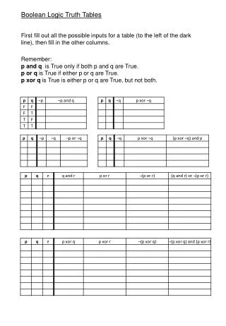
Logic gates are the fundamental building blocks of digital circuits. They perform logical operations on binary inputs (0s and 1s) and produce a single binary output based on predefined rules. The most common logic gates include AND, OR, NOT, NAND, NOR, XOR, and XNOR. Each gate follows a specific Boolean function, which can be represented using a truth tableu2014a table that lists all possible input combinations and their corresponding outputs.

E N D
Logic Gates Dr Anita Choudhary Assistant Professor Department of Computer Science anitach312@gmail.com
Logic Gate • A logic gate is an elementary building block of a Digital Circuit. • Logic gates are the fundamental components of all digital circuits and systems. • In digital electronics, there are seven main types of logic gatesused to perform various logical operations. • A logic gate is basically an electronic circuit designed by using components like diodes, transistors, resistors, capacitors, etc., and capable of performing logical operations. • Most logic gates have two inputs and one output. • Every terminal is in one of the two Binary Digits (0) or (1) • Low state approximately zero volts (0 volts) • High state approximately five volts (+5 volts)
Types of Logic Gates A logic gate is a digital gate that allows data to be manipulated. Logic gates, use logic to determine whether or not to pass a signal • The logic gates can be classified into the following major types: 1. Basic Logic Gates : There are three basic logic gates: • AND Gate • OR Gate • NOT Gate 2. Universal Logic Gates : In digital electronics, the following two logic gates are considered as universal logic gates: • NOR Gate • NAND Gate 3. Derived Logic Gates : The following two are the derived logic gates used in digital systems: • XOR Gate • XNOR Gate
AND Gate • An AND gate accepts two input signals • If the two input values for an AND gate are both 1, the output is 1; otherwise, the output is 0
AND Gate • A binary arrangement with two switches in series
OR Gate • If the two input values are both 0, the output value is 0, otherwise, the output is 1
OR Gate • A binary arrangement with two switches in parallel
NOT Gate • A logical inverter , sometimes called a NOT gate to differentiate it from other types of electronic inverter devices, has only one input. • The NOT function is not a decision making logic gate like the AND, or OR gates, but instead is used to invert or complement a digital signal.
XOR Gate • XOR, or exclusive OR, gate • An XOR gate produces 0 if its two inputs are the same, and a 1 otherwise • Note the difference between the XOR gate and the OR gate; they differ only in one input situation • When both input signals are 1, the OR gate produces a 1 and the XOR produces a 0
XOR Gate XOR Gate having two AND, one OR and two NOT Gates
NAND Gate • A NAND gate produces the opposite results of an AND gate
NOR Gate • A NOR gate produces the opposite results of an OR gate
XNOR Gate • A NOR gate produces the opposite results of an XOR gate
XNOR Gate XNOR Gate is combination of XOR and NOT Gate
Uses of Gates • Use for doorbell • Use in smoke sensors • Use in traffic lights • Use in mobile or calculators • Use in UPS chips