IJETR
40 likes | 73 Views
ER Publication,<br> IJETR, IJMCTR,<br> Journals,<br> International Journals,<br> High Impact Journals, <br>Monthly Journal, <br>Good quality Journals,<br> Research, <br>Research Papers,<br> Research Article, <br>Free Journals, Open access Journals, <br>erpublication.org,<br> Engineering Journal,<br> Science Journals,

IJETR
E N D
Presentation Transcript
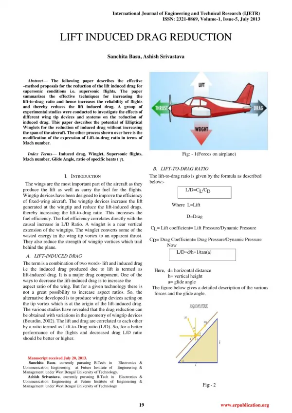
International Journal of Engineering and Technical Research (IJETR) ISSN: 2321-0869, Volume-1, Issue-5, July 2013 LIFT INDUCED DRAG REDUCTION Sanchita Basu, Ashish Srivastava Abstract— The following paper describes the effective –method proposals for the reduction of the lift induced drag for supersonic conditions i.e. supersonic flights. The paper summarizes the effective techniques for increasing the lift-to-drag ratio and hence increases the reliability of flights and thereby reduces the lift induced drag. A group of experimental studies were conducted to investigate the effects of different wing tip devices and systems on the reduction of induced drag. This paper describes the potential of Elliptical Winglets for the reduction of induced drag without increasing the span of the aircraft. The other process shown over here is the modification of the expression of Lift-to-drag ratio in terms of Mach number. Index Terms—Induced drag, Winglet, Supersonic flights, Mach number, Glide Angle, ratio of specific heats ( γ). Fig: - 1(Forces on airplane) B.LIFT-TO-DRAG RATIO The lift-to-drag ratio is given by the formula as described below:- Where L=Lift D=Drag CL= Lift coefficient= Lift Pressure/Dynamic Pressure CD= Drag Coefficient= Drag Pressure/Dynamic Pressure Now L/D=d/h=1/tan(a) I.INTRODUCTION The wings are the most important part of the aircraft as they produce the lift as well as carry the fuel for the flights. Wingtip devices have been designed to improve the efficiency of fixed-wing aircraft. The wingtip devices increase the lift generated at the wingtip and reduce the lift-induced drags, thereby increasing the lift-to-drag ratio. This increases the fuel efficiency. The fuel efficiency correlates directly with the causal increase in L/D Ratio. A winglet is a near vertical extension of the wingtips. The winglet converts some of the wasted energy in the wing tip vortex to an apparent thrust. They also reduce the strength of wingtip vortices which trail behind the plane. L/D=CL/CD A.LIFT-INDUCED DRAG The term is a combination of two words- lift and induced drag i.e the induced drag produced due to lift is termed as lift-induced drag. It is a major drag component. One of the ways to decrease the lift-induced drag is to increase the aspect ratio of the wing. But for a given technology there is not a great possibility to increase aspect ratios. So, the alternative developed is to produce wingtip devices acting on the tip vortex which is at the origin of the lift-induced drag. The various studies have revealed that the drag reduction can be obtained with variations in the geometry of wingtip devices (Bourdin, 2002). The lift and drag are correlated to each other by a ratio termed as Lift-to-Drag ratio (L/D). So, for a better performance of the flights and decreased drag L/D ratio should be better or higher. Here, d= horizontal distance h= vertical height a= glide angle The figure below gives a detailed description of the various forces and the glide angle. Manuscript received July 20, 2013. Sanchita Basu, currently pursuing B.Tech in Electronics & Communication Engineering at Future Institute of Engineering & Management under West Bengal University of Technology. Ashish Srivastava, currently pursuing B.Tech in Electronics & Communication Engineering at Future Institute of Engineering & Management under West Bengal University of Technology Fig:- 2 19 www.erpublication.org
LIFT INDUCED DRAG REDUCTION A.USE OF ELLIPTICAL WINGLETS The various types of winglets available are triangular, quadrilateral, half-circular, raked, blended etc. Recently, an experimental study has been done on three different types (rectangular, triangular and circular) of winglet (Inam, et al. 2010) to see the potential of winglets for the reduction of induced drag without increasing the span of the aircraft (see Figure 13). The experimental results show that the drag decreases by 26.4%-30.9% for the aircraft model with winglet for the maximum Reynolds number considered in their studies. But these have certain disadvantages which have been overcome by elliptical winglets. The figure below shows the structure of elliptical winglet- Now for supersonic conditions, L/Dmax=4(M+3)/M Where M= Mach Number Mach Number= speed of object/speed of sound. For supersonic conditions, 1.2<M<5.0. Mach Number is derived from Bernoulli’s Equation c q p 2/7 5[( 1) 1] M Where, qc= dynamic pressure P=static pressure SO FOR A BETTER RELIABILITY AND REDUCTION OF LIFT INDUCED DRAG L/D RATIO SHOULD BE HIGHER I.E. FOR A LOWER MACH NUMBER WE SHOULD GET A BETTER L/D RATIO Fig:- 4 Fig:- 3 Now as we know L/D ratio is related to angle of attack so Mach Number can be related to the angle of attack in a following way:- tan a= M/4(M+3) So our research is based on the relation of this angle of attack and Mach Number. II.PROPOSEDWORKFORDRAGREDUCTION We have proposed two ways for reduction of the lift-induced drag. They are- 1.Use of Elliptical winglets 2.Modification of the expression of the L/D Ratio. First approach is the use of elliptical winglets instead of other types of winglets like triangular, quadrilateral, half-circular. The second part describes the modification of the expression of L/D Ratio. Fig: -5 The figure 5 and 6 shown above shows the structure of elliptical winglet and its comparison with blended winglet. 20 www.erpublication.org
International Journal of Engineering and Technical Research (IJETR) ISSN: 2321-0869, Volume-1, Issue-5, July 2013 2 v gh Velocity of free stream or air, Here, g=Acceleration due to gravity h=Pressure in the air stream Again, Pressure in the air stream, Here, Δp = Difference of pressure = Specific weight Advantages of elliptical winglet over other winglets:- 1.They reduce wingtip vortices, the twin tornados formed by the difference between the pressure on the upper surface of an airplane's wing and that on the lower surface. Winglets produce an especially good performance boost for jets by reducing drag, and that reduction could translate into marginally higher cruise speed. 2.The lift distribution curve for various winglets is shown below:- / h Fig:- 6 The figure 6 shows the comparison of vortex pattern of an elliptical winglet with a wing with no winglet. The actual vortex pattern is as follows- Fig: -7 So the designed aircraft model is:- Fig: -8 Lift to Drag ratio was calculated by using the measured lift and drag forces. Reynolds number, Where, ρ=Density of free stream or air v=Velocity of free stream or air l=Model length μ=Dynamic viscosity To calculate the Reynolds number at first we have to measure the velocity of the free stream of air .To measure the velocity the pressure is measured by a inclined manometer which pressure tube is connected into the wind tunnel. Now, Observations from graph: - The elliptical winglet has uniform lift distribution as compared to rectangular winglet which has less lift. So from the above study it is clear that the elliptical winglets are beneficial over other types of winglets and they should be used in the supersonic flights to reduce drag. R= ρvl/μ B.MODIFICATION OF THE EXPRESSION OF MACH NUMBER As we have seen earlier the relation of Mach Number and glide angle is as follows: - 21 www.erpublication.org
LIFT INDUCED DRAG REDUCTION L/d=tan a= M/4(M+3) Reduction of induced drag without increasing the span of the aircraft. So we have to suggest the Elliptical shape of winglet for the maximum lift and minimum drag among the other shapes. FUTURE WORK There is lot of work to be done on the incorporation of the term γ in the expression of L/D ratio. The size of the elliptical winglet has to be further studied to give a better performance. We are working on the hybrid winglet shape consisting of rectangular and elliptical which can be much more beneficial. Now for M=1.5, a=4.763°, L/D=12.00 for M=2, a=5.71°, L/D=10.00 So our proposed expression is as follows: - L/D=TAN A=M/4(M+3)? ? Where, γ is the ratio of specific heats i.e. Cp /Cv; Cp= heat capacity at constant pressure Cv = heat capacity at constant volume Now we calculate the angle from the modified expression: - For M=1.5, a=3.4°, L/D=16.83 M=2, a=4.08°, L/D=14.019 Thus we observe that for a given Mach Number 1.L/D ratio increases 2.Angle of attack decreases which enhances L/D ratio The earlier studies were carried out by fixing the angle as 5°, but now for the same angle we get a better L/D ratio. So the given expression proves beneficial for the reduction of lift-induced drag as the L/D ratio becomes better. The reason for incorporating the term γ in the expression is:- The air molecules have a particular energy. When an object is gliding through the air, the molecules start to vibrate due to the friction and difference of molecular energy, thus the energy gets converted into the kinetic energy. The kinetic energy results in the generation of the heat which gives rise to the basis of incorporating the term in the expression. REFERENCES 1.John D. Anderson, J.R, “Introduction to Flight”, Third Edition, Mc Graw--Hill International editions, Aerospace Science Series 2.Dr. P. N. Modi & Dr. S. M Seth, “Hydraulics and Fluid Mechanics Including Machine” (In SI Unit), new edition 2005-2006, Standard Book House. 3.Dr. K. R. Arora, Fluid Mechanics, “Hydraulics and Hydraulic Machine” (In SI Unit), Ninth revised and enlarged edition August 2005, Standard Publishers Distributors. 4.William H. Rae, Jr. & Alan pope, “Low Speed Wind Tunnel Testing”, Second Edition, A Wiley – Inter science Publication 5.International Journal of Mechanical & Mechatronics IJMME-IJENS Vol: 10 No: 03 6. Aircraft Drag Reduction: An Overview by MOHSEN JAHANMIRI. 7.Wingtip Devices (http:/ / www. boeing. com/ commercial/ aeromagazine/ aero_17/ wingtip_devices. html)." Faye, R.; Laprete, R.; Winter, M. Aero, No. 17., Boeing. 8. Aviation Week & Space Technology, February 23, 2009, "Working Winglets", p. 39. 9." Airbus to test new winglets for single-aisle jetliners (http:/ / www. boeing. com/ news/ frontiers/ archive/ 2006/ march/ i_iw. Html)." III.CONCLUSION 10.David Noland, "Steve Fossett and Burt Rutan's Ultimate Solo: Behind the Scenes", Popular. Elliptical Winglets have the potential to give the following benefits: 1. Reduced climb thrust. A winglet equipped aircraft can typically take a 3% derate over the non-winglet equivalent aircraft. This can improve engine life and reduce maintenance costs. 2. Improved cruise performance. Winglets can allow aircraft to reach higher levels sooner. 3. Elliptical winglet at an inclination has the better performance giving as compared to other configurations for a given Mach Number and Glide Angle. Sanchita Basu, currently pursuing B.Tech in Electronics & Communication Engineering at Future Institute of Engineering & Management under West Bengal University of Technology. Her research interest includes control system and radar engineering Ashish Srivastava, currently pursuing B.Tech in Electronics & Communication at Future Institute of Engineering & Management under West Bengal University of Technology. His research interest includes control system and wireless communication. Engineering 22 www.erpublication.org