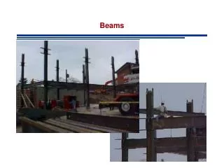
load on beams
calculation for beam designs


load on beams
E N D
Presentation Transcript
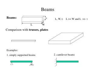
Loads and beams Dr Andrew Kimmance
Loaded Beam F F/2 F/2 The reactions at the end supports with the load at the centre are F/2
Shear force diagram Maximum shear force = reaction force
Bending moment diagram The Maximum bending moment due to the load if found by calculating the area under the Shear Force Diagram between zeros This could be written as FL/4 The area is (L/2) x (F/2) (area of triangle ½ base x height)
UDL (Uniformly Distributed Load) The UDL (Uniformly Distributed Load) of a beam is found by the mass per metre by the length and g(gravitational field strength) UDL = (kg/m) x g x L (which is weight per metre x length)
mid span moment (Due to weight of beam) (L/2) = Length form end of beam to midpoint The equation for mid span moment is (FL/4) x (L/2) FL2/8 or wt x L2/8
Maximum design loading Maximum design loading (M design) is the Maximum bending moment due to the load plus the mid span (bending) moment (Due to weight of beam)
Elastic section modulus of a beam The elastic section modulus of a beam is the ratio of the maximum bending moment, M to the maximum allowable stress, . That is, elastic section modulus = maximum bending moment / maximum allowable stress (sigma, σ) z=M/σ (m3)
Second Moment of Area • Area Moment of Inertia, also known as Second Moment of area - I, is a property of shape that is used to predict deflection, bending and stress in beams.
The second moment of area • The second moment of area • I = ∫y2dA • where dA is a thin section of the area taken as a slice parallel to the neutral axis, and y is the distance separating that slice from the neutral axis.
The second moment of area • I (second moment of area) can also be found using the equation Z (elastic section modulus ) x Y (depth to neutral axis) • Equation forms • I = Z x y • Y = I/Z • Z = I/Y
Table 1 Square hollow section 30 x 30 x 3.5
Table 2 Universal beam 470 x 205 x 54
Worked example Q1 An overhead gantry in a workshop is of the form shown in Figure 1 below. It is required to lifta light goods vehicle of mass 6000kg. Fig 1 60o (all) 3m 3m • C • B A
Worked example Q1 • a) Convert the loading to kN and calculate the reactions at the end supports. (g = 9.81m/s2) • 6000kg x 9.81 = 58.86 kN • Load is at the centre so the reactions at the end supports are half the load = 29.43kN
Worked example Q1 • Show that the maximum force (tensile or compressive) in any member is 33.98 kN. 29.43kN Max Force in 60o member = 29.43/sin 60 = 33.98kN 60o Max force in horizontal member force = 33.98 x cos60 =16.99kN
Worked example Q1 All of the members in the truss are 30 x 30 x 3.5 square hollow sections. Using the data in Table 1 find the cross-sectional area and calculate the maximumaxial stress in the section.
Worked example Q1 • Area of section = 3.71cm2 • Max load is 33.98kN • Max stress = 33.98/3.71 = 9.16kN/cm2
Worked example Q1 • Safety factor = maximum allowable stress/working stress • The maximum allowable stress in this example is 27.5 kN/cm2 • The working stress is 9.16 kN/cm2 • Safety factor = 27.5/9.16 = 3
Worked example Q1 • It is decided that a factor of safety of 3.5 is required for the gantry in Question 1. The truss is to be replaced with a universal beam of section 470 x 205 x 54 • (see Table 2) and of the same length as the span of the truss in Question 1.
Worked example Q2 • Draw shear force and bending moment diagrams for the 6000kg loading case.
Worked example Q2 Shear Force Diagram 29.43kN - 29.43kN
Worked example Q2 Bending moment diagram 29.43kN Bending moment due to imposed load 6m • The area is (L/2) x (F/2) (area of triangle ½ base x height) • =29.43 x 3 = 88.29kNm
Worked example Q2 • Convert the mass per metre of the beam into a distributed load and calculate the maximum mid-span moment in the beam due to this load. Add this to the maximum moment due to the imposed load to find the maximum design loading.
Worked example Q2 • UDL = 54 x9.81 N/m • 529.74N/m Mid span moment FL2/8 or wt x L2/8 • 529.74x 36/8 • 2.38 kNm
Worked example Q2 Maximum design loading (M design) is the Maximum bending moment due to the load plus the mid span (bending) moment (Due to weight of beam)
Worked example Q2 • = 88.29kNm + 4.74kNm • = 90.67kNm
Worked example Q2 • Find values for the second moment of area Ixx and the elastic section modulus zxxfrom table 2 and hence calculate the depth to the neutral axis, y.
Worked example Q2 • Y = I/Z • 22500cm4/1200cm3 • 18.75cm • Or 187.5mm
Worked example Q2 • Using the formula Mdesign= σcalculate the I Y maximum bending stress in the beam
Worked example Q2 • Stress (σ) =(Mdesign x Y)/I • =90.67 x106Nmm x 187.5mm 225 x 106mm4 • = 75.56N/mm2
Worked example Q2 • Calculate the factor of safety for this arrangement assuming the maximum allowable stress in 275N/mm2.
Worked example Q2 • Safety factor 275/75.56 = 3.64