Download
1 / 86
0 likes | 14 Views
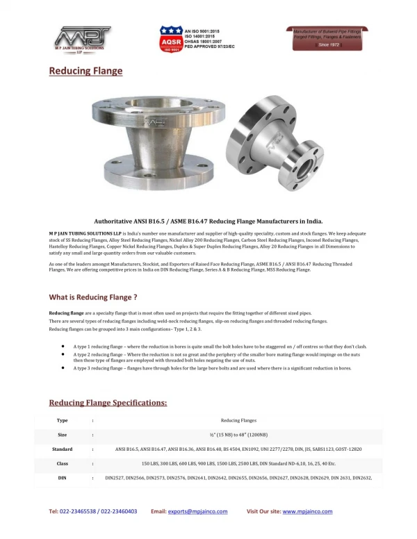
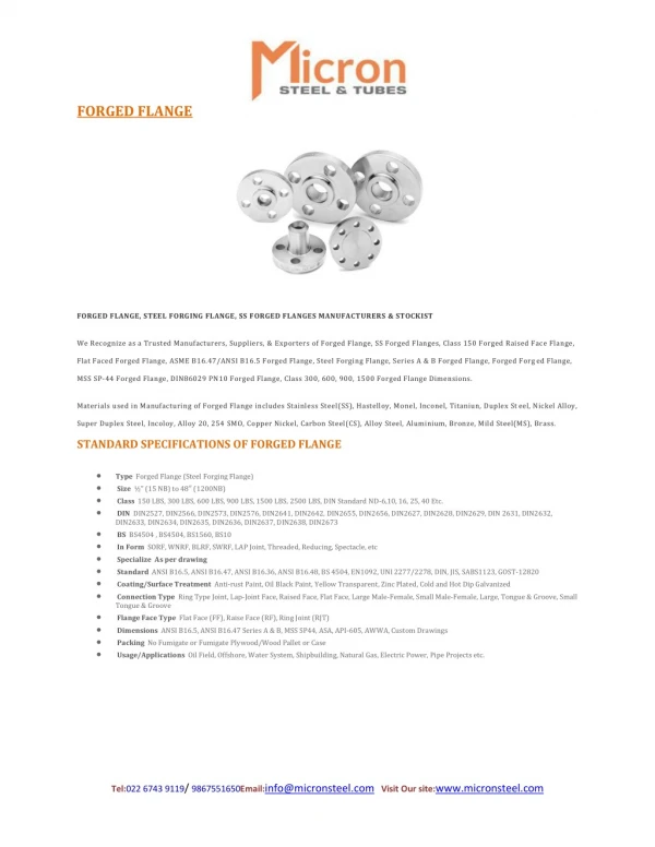
Flange dimensions are determined by the pipe size and the pressure class required for the application. As a leading manufacturer & supplier of different flanges, Steels and alloys We provide high quality products and it is suitable for your industry with the correct sizes.

E N D
FLANGES EXPERTISE 9/A, 9th Floor, Mehta Mehal, 15th Mathew Road, Opera House, Charni Road, Mumbai - 400 004, India. web: www.aesteiron.com email: info@aesteiron.com Tel: +91-22-67776700 - 6799 - 6777 #
'AESTEIRON Steels LLP' is a leading manufacturer and distributor who deals in various steel products such as stainless steel, alloy steel, carbon steel, nickel & special metals alloys. Our products are broadly valued for its outstanding fabrication and finishing, sturdiness and cost effectiveness. It is equipped with an experience of over 4 decades in industrial steel & executing over 100 large projects satisfactorily, we have emerged as a leading producer of pipes & pipes fittings that are quality certified by TUV Rheinland (INDIA), PED & ISO 9001: 2015. 'AESTEIRON Steels LLP' has begun its journey in the year 2007. We make sure that we offer the best quality products by latest industry standards along with modern technologies. Our product line represents the highest standard in productivity and reliability terms. Our products are procured from certified vendors in the market who offer quality standard products with competitive prices. 'AESTEIRON Steels LLP' is a client focused company - we purely value our customer requirements and expectation, which is evident with the growing consumer base over the years as we consistently strive to enrich our customer experience. For more information on the types and material of industrial flanges we have to offer, you can visit our website- and find the specific details under the Products section > Flanges. www.aesteiron.com For accurate stainless steel flange weight calculation, we also offer on our website a trusted Blind Flange / WNRF Flange Weight Calculator. In case there arises a need help in identifying the product range that we have to offer and which flange best suits your application, feel free to contact us.
AESTEIRON (STEELS) FLANGE PRODUCT HANDBOOK FLANGES : Facing Type/ Face Finish/ Manufacturing Facilities/ Testing Facilities 02 Forged Flanges - ASME B16.5 Class 150 300 400 600 900 1500 2500 03 - 09 Forged Flanges - ASME B16.5 Weight Table / (Approx) 150 300 400 600 900 1500 2500 11 - 14 Dimensional Tolerances According to ASME B16.5 15 - 16 Stud & Bolt Dimensions - ASME B16.5 17 Studs & Bolts - ASME B16.47 18 Welding Neck Flange & Blind Flange - ASME B16.47 Series A Class 150 300 400 600 900 19 - 23 Welding Neck Flange & Blind Flange - ASME B16.47 Series B Class 75 150 300 400 600 900 24 - 29 ASME B16.47 Modified as per Industry Standard to Slip on 31 - 33 ASME B16.1 Category - Class 125LW, 125SO, 125WN, 250 34 - 37 Slip-on & Blind, Weld Neck Flanges - ASME B16.47 Class 75SO, 75WN, 175,350 39 - 44 Welding Neck flange/ Slip-on Flange/ Threaded Flange - ASME B16.36 Class 300 45 - 47 Welding Neck Orifice Flanges - ASME B16.36 Class 400 600 900 1500 2500 49 - 53 Detailed Sizes of Jack Screw Sizes For Orifice Flanges 54 AWWA Standard grade Steel - Class 2B, 2D, 3D 4E, 5E, 6F 55 - 60 ASME B16.5 Long Welding Neck Flanges - 150, 300, 400, 600, 900, 1500, 2500 62 - 68 ASME Studding Outlets - 150, 300, 600, 900, 1500, 2500 69 - 74 ASME B16.5 Standard - List of Material Specifications for process of flanges 76 - 79 Wall Thickness & Welding Neck Dimensions of Flange Bore - ASME B16.5 80 - 81 Ring - Joint Facings Flanges Dimensions - ASME B16.5 82 - 83 # 1 www.aesteiron.com info@aesteiron.com
FLANGE–FACING TYPES : Flat–face (FF), Raised face, Large Raised face, Ring Type Joint (RTJ), Tongue & Groove face (T&G) (large & small), Male-Female face FLANGE FACE FINISH : Stock Finish (Serration), Concentric Serrated, Spiral/ Continuous/ Phonographic Serrated, Smooth Finish. MANUFACTURING FACILITIES : 1. 2. 3. 4. 5. Band Saw Machines to cut raw material from 25 mm to 1150 mm Forge: cold forging, impression die forging, open die forging, seamless rolled ring forging. Machinable Flanges: blind lens rings, full face, flange plus connections, raised face, ring groove. Drilling : VMC, radial drill/ column drill machines Heating : Annealing Solution TESTING FACILITIES : 1. 2. 3. 4. 5. 6. 7. 8. 9. 10. Dye penetrate test of Flanges Spectra Analyser (PMI test) Ultrasonic testing machine Radiation servo meter - Dynamic radiation detection system - Gramma ray spectroscopy - Portable radiation detection Tensile Test computerised Roughness Testing on Surface Impact Test Hardness Test Microscope facility IGC Test 2 www.aesteiron.com info@aesteiron.com
Forged Flanges - ASME B16.5 Class 150 WELD NECK SLIP-ON THREADED D F D L E2 I2 D I B Opr B I B E C A C A C A 1/16" 1/16" 1/16" ASME B16.5 WNRF FLANGES ASME B16.5 SORF FLANGES ASME B16.5 THREADED FLANGES SOCKET WELD LAP JOINT BLIND D E K D E3 BI B I3 BR j E2 C A 1/16" C A 1/16" A ASME B16.5 SWRF FLANGES ASME B16.5 LAP JOINT FLANGES ASME B16.5 BLRF FLANGES Diameter of Bolt Holes (Inch.) Bolt Circle (Inch.) NPS (Inch.) E3 BR I2 j 4 3 I3 E2 A B C D E F I K Opr 0.62 1.19 4-0.62 2.38 0.88 0.90 0.84 0.56 1.81 0.62 0.12 0.38 0.62 3.50 0.44 1.38 ½ 0.38 1.50 2.75 1.05 0.56 4-0.62 1.09 0.82 2.00 0.62 0.12 0.44 0.62 1.11 0.44 0.50 1.69 ¾ 3.88 1.05 2.12 0.69 0.12 0.50 0.69 1.94 4-0.62 3.12 1.36 1.38 1.32 0.62 0.56 2.00 4.25 0.50 1 2.31 4-0.62 3.50 1.70 1.38 1.66 0.75 2.19 0.81 0.19 0.56 0.81 1.72 0.62 2.50 1¼ 4.62 0.56 2.56 4-0.62 3.88 1.95 1.61 1.97 1.90 0.81 2.38 0.88 0.25 0.62 0.88 0.69 2.88 1½ 5.00 0.62 4.75 4-0.75 3.06 2.07 2.46 2.38 0.94 2.44 1.00 0.31 0.69 1.00 2.44 0.75 3.62 6.00 0.69 2 3.56 4-0.75 5.50 2.69 1.12 0.31 0.75 1.12 2.94 2.97 3.60 2.88 1.06 2.47 0.88 7.00 2½ 0.81 4.12 2.69 1.19 0.38 0.81 1.19 3.57 4.25 4-0.75 6.00 3.07 1.12 0.94 5.00 3 7.50 0.88 3.50 4.00 4.81 8-0.75 7.00 4.07 3.55 4.10 1.19 2.75 1.25 0.38 0.88 1.25 0.94 5.50 3½ 8.50 0.88 4.57 5.31 7.50 4.50 1.25 4.03 4.60 2.94 1.31 0.44 0.94 1.31 8-0.75 0.94 6.19 0.88 4 9.00 8.50 5.66 5.05 5.69 5.56 6.44 8-0.88 1.38 3.44 1.44 0.44 0.94 1.44 5 0.94 7.31 10.00 0.88 7.56 8-0.88 9.50 6.72 6.07 6.75 6.63 1.50 3.44 1.56 0.50 1.06 1.56 1.00 8.50 6 11.00 0.94 3.94 1.75 0.50 1.25 1.75 9.69 8-0.88 8.72 7.98 8.75 8.63 1.69 10.62 8 13.50 1.06 1.12 11.75 14.25 10.88 10.02 10.92 10.75 3.94 1.94 0.50 1.31 1.94 12.75 12.00 12-1.00 1.88 1.19 16.00 10 1.12 12.88 12.00 12.92 12.75 4.44 2.19 0.50 1.56 2.19 15.00 14.38 12-1.00 17.00 2.12 1.25 19.00 1.19 12 16.25 15.75 18.75 14.14 13.25 14.18 14.00 2.19 4.94 3.12 0.50 1.63 2.25 12-1.12 1.38 21.00 14 1.31 4.94 3.44 0.50 1.75 2.50 18.50 18.00 16-1.12 21.25 16.16 15.25 16.19 16.00 2.44 16 23.50 1.38 1.44 5.44 3.81 0.50 1.94 2.69 16-1.25 22.75 18.18 17.25 18.20 18.00 21.00 19.88 1.56 18 25.00 1.50 2.62 2.81 20-1.25 25.00 20.20 19.25 20.25 20.00 5.62 4.06 0.50 2.13 2.88 23.00 22.00 1.69 27.50 1.62 20 25.25 24.25 20-1.38 27.25 22.22 21.25 22.25 22.00 3.07 5.82 4.25 0.50 2.38 3.13 1.81 29.50 1.75 22 27.25 26.12 20-1.38 29.50 24.25 23.25 24.25 24.00 3.19 5.94 4.38 0.50 2.50 3.25 1.88 32.00 1.81 24 # 3 www.aesteiron.com info@aesteiron.com
Forged Flanges - ASME B16.5 Class 300 WELD NECK SLIP-ON THREADED D F D L E2 I2 D I B Opr B I B E C A C A C A 1/16" 1/16" 1/16" ASME B16.5 WNRF FLANGES ASME B16.5 SORF FLANGES ASME B16.5 THREADED FLANGES SOCKET WELD LAP JOINT BLIND D E K D E3 BI B I3 BR j E2 C A 1/16" C A 1/16" A ASME B16.5 SWRF FLANGES ASME B16.5 LAP JOINT FLANGES ASME B16.5 BLRF FLANGES Diameter of Bolt Holes (Inch.) Bolt Circle (Inch.) NPS (Inch.) E3 BR I2 Opr j 4 3 I3 E2 A B C D E F I L K 3.75 0.50 0.56 1.50 ½ 1.38 4-0.63 2.62 0.88 0.62 0.90 0.84 0.81 2.00 0.88 0.12 0.93 0.38 0.62 ¾ 4.62 0.56 0.62 1.69 1.88 4-0.75 3.25 1.09 1.05 0.94 2.19 1.00 0.12 1.14 0.44 0.62 0.82 1.11 4.88 0.62 0.69 2.00 4-0.75 3.50 1.36 1.05 1.38 1.32 1.00 2.38 1.06 0.12 1.41 0.50 0.69 1 2.12 2.50 5.25 2.50 4-0.75 1¼ 0.69 0.75 3.88 1.70 1.66 1.00 2.50 1.06 0.19 1.75 0.56 0.81 1.38 1.72 2.75 4.50 1.95 1½ 6.12 0.75 0.81 2.88 4-0.88 1.61 1.97 1.90 1.13 2.63 1.19 0.25 1.98 0.62 0.88 6.50 0.81 0.88 3.62 3.31 8-0.75 5.00 2.07 2.46 2.38 1.25 2.69 1.31 0.31 2.50 0.69 1.12 2 2.44 2½ 7.50 0.94 1.00 3.94 8-0.88 5.88 2.94 2.47 2.97 2.88 1.44 2.94 1.50 0.31 3.00 0.75 1.25 4.12 8.25 5.00 3.57 3.50 1.63 3.06 1.69 0.38 3.63 0.81 .... 1.25 3 4.62 8-0.88 6.62 3.07 3.60 1.06 1.12 5.50 5.25 7.25 3½ 9.00 8-1.00 4.07 3.55 4.10 4.00 1.69 3.13 1.75 0.38 4.13 1.44 1.12 1.19 .... 5.75 4.57 4 10.00 1.19 1.25 6.19 8-1.00 7.88 4.03 4.60 4.50 1.82 3.32 1.88 0.44 4.63 1.44 .... 5 11.00 1.31 1.38 7.31 7.00 8-1.00 9.25 5.66 5.05 5.69 5.56 1.94 3.82 2.00 0.44 5.69 1.69 .... 12.50 1.38 1.44 8.50 6.07 6.75 6 8.12 12-1.00 10.62 6.72 6.63 2.00 3.82 2.06 0.50 6.75 1.81 .... 15.00 10.25 7.98 8.75 8 1.56 1.62 10.62 13.00 8.72 8.63 2.38 4.32 2.44 0.50 8.75 2.00 12-1.12 .... 10 17.50 1.81 1.88 12.75 12.62 16-1.25 15.25 10.88 10.02 10.92 10.75 2.56 4.56 3.75 0.50 10.88 2.19 .... 14.75 17.75 20.50 1.94 2.00 15.00 16-1.38 12.88 12.00 12.92 12.75 2.82 5.06 4.00 0.50 12.94 2.38 12 .... 16.25 16.75 20.25 23.00 20-1.38 13.25 14.18 14.00 2.94 14 14.14 5.56 4.38 0.50 14.19 2.50 2.06 2.12 .... 25.50 2.19 2.25 18.50 20-1.50 22.50 16 19.00 16.16 15.25 16.19 16.00 3.19 5.69 4.75 0.50 16.19 2.69 .... 18 28.00 2.31 2.38 21.00 21.00 24-1.50 24.75 18.18 17.25 18.20 18.00 3.44 6.19 5.12 0.50 18.19 2.75 .... 20 30.50 2.44 2.50 23.00 23.12 24-1.62 27.00 20.20 19.25 20.25 20.00 3.69 6.32 5.50 0.50 20.19 2.88 .... 33.00 2.57 2.63 25.25 25.25 24-1.75 29.25 21.25 22.25 22.00 3.93 6.43 5.75 0.50 22.19 3.13 22 22.22 .... 2.69 2.75 27.25 24.25 23.25 24.25 36.00 27.62 24-1.88 32.00 24.00 4.13 6.56 6.00 0.50 24.19 3.25 24 4 www.aesteiron.com info@aesteiron.com
Forged Flanges - ASME B16.5 Class 400 WELD NECK SLIP-ON THREADED D F D L E2 I2 D I B Opr B I B E C A C A C A 1/4" 1/4" 1/4" ASME B16.5 WNRF FLANGES ASME B16.5 SORF FLANGES ASME B16.5 THREADED FLANGES SOCKET WELD LAP JOINT BLIND D E K D E3 BI B I3 B j E2 C A 1/4" C A 1/4" A ASME B16.5 SWRF FLANGES ASME B16.5 LAP JOINT FLANGES ASME B16.5 BLRF FLANGES Diameter of Bolt Holes (Inch.) Bolt Circle (Inch.) NPS (Inch.) E3 C I2 j 4 3 I3 E2 A B D E F I L K Opr ½ 3.75 0.56 1.38 1.50 4-0.63 2.62 0.88 0.90 0.84 0.88 2.06 0.88 0.12 0.93 0.38 0.62 ¾ 4.62 0.62 1.69 1.88 4-0.75 3.25 1.09 1.05 1.00 2.25 1.00 0.12 0.44 0.62 1.11 1.14 4.88 0.69 2.00 4-0.75 3.50 1.36 1.38 1.32 1.06 2.44 1.06 0.12 0.50 0.69 1 2.12 1.41 1¼ 5.25 0.81 2.50 2.50 4-0.75 3.88 1.70 1.66 2.62 1.12 0.19 1.75 0.56 0.81 1.72 1.12 1½ 6.12 0.88 2.88 2.75 4-0.88 4.50 1.95 1.97 1.90 1.25 2.75 1.25 0.25 1.99 0.62 0.88 1.00 3.62 3.31 8-0.75 5.00 2.46 2.38 2.88 1.44 0.31 2.50 0.69 1.12 2 2.44 1.44 6.50 7.50 2½ 3.94 8-0.88 5.88 2.94 2.97 2.88 1.62 3.12 1.62 0.31 3.00 0.75 1.25 1.12 4.12 Purchaser Specification required 3 8.25 1.25 5.00 4.62 8-0.88 6.62 3.57 3.60 3.50 1.81 3.25 1.81 0.38 3.63 0.81 1.38 …. 3½ 9.00 1.38 5.50 5.25 8-1.00 7.25 4.07 4.10 4.00 1.94 3.38 1.94 0.38 4.13 1.56 …. …. 5.75 4.57 10.00 1.38 6.19 8-1.00 7.88 4.60 4.50 2.00 3.50 2.00 0.44 4.63 4 1.44 …. …. 5 11.00 1.50 7.31 7.00 8-1.00 9.25 5.66 5.69 5.56 4.00 2.12 0.44 5.69 …. 6.75 …. 8.75 …. 10.88 1.69 2.12 …. …. 6 12.50 1.62 8.50 8.12 12-1.00 10.62 6.72 6.75 6.63 2.25 4.06 2.25 0.50 1.81 …. …. 8 15.00 1.88 10.62 10.25 13.00 8.72 8.75 8.63 2.69 4.62 2.69 0.50 2.00 12-1.12 …. …. 10 17.50 12.75 12.62 16-1.25 15.25 10.88 10.92 10.75 2.88 4.88 4.00 0.50 2.19 2.12 …. …. 20.50 2.25 15.00 14.75 16-1.38 17.75 12.88 12.92 12.75 3.12 5.38 4.25 0.50 12.94 2.38 12 …. …. 23.00 2.38 16.25 16.75 20-1.38 20.25 14.18 14.00 3.31 5.88 4.62 0.50 14.19 2.50 14 14.14 …. …. 16 25.50 2.50 18.50 19.00 21.00 21.00 20-1.50 22.50 16.16 16.19 16.00 3.69 6.00 5.00 0.50 16.19 2.69 …. …. 18 28.00 2.62 24-1.50 24.75 18.18 18.20 18.00 3.88 6.50 5.38 0.50 18.19 2.75 …. …. 6.62 5.75 0.50 20 30.50 2.75 23.00 23.12 24-1.62 27.00 20.20 20.25 20.00 4.00 20.19 .... 2.88 …. …. …. 33.00 2.88 25.25 25.25 24-1.75 29.25 22.25 22.00 4.25 6.75 6.00 0.50 22 22.22 …. …. 36.00 3.00 27.25 27.62 24-1.88 32.00 24.25 24.25 24.00 4.50 6.88 6.25 0.50 24.19 3.25 24 # 5 www.aesteiron.com info@aesteiron.com
Forged Flanges - ASME B16.5 Class 600 WELD NECK SLIP-ON THREADED D F D L E2 I2 D I B Opr B I B E C A C A C A 1/4" 1/4" 1/4" ASME B16.5 WNRF FLANGES ASME B16.5 SORF FLANGES ASME B16.5 THREADED FLANGES SOCKET WELD LAP JOINT BLIND D E K D E3 BI B I3 B j E2 C A 1/4" C A 1/4" A ASME B16.5 SWRF FLANGES ASME B16.5 LAP JOINT FLANGES ASME B16.5 BLRF FLANGES Diameter of Bolt Holes (Inch.) Bolt Circle (Inch.) NPS (Inch.) E3 C I2 j 4 3 I3 E2 A B D E F I L K Opr ½ 3.75 0.56 1.38 1.50 4-0.63 2.62 0.88 0.90 0.84 0.88 2.06 0.88 0.12 0.93 0.38 0.62 ¾ 4.62 0.62 1.69 1.88 4-0.75 3.25 1.09 1.11 1.05 1.00 2.25 1.00 0.12 1.14 0.44 0.62 1 4.88 0.69 2.00 2.12 4-0.75 3.50 1.36 1.38 1.32 1.06 2.44 1.06 0.12 1.41 0.50 0.69 1¼ 5.25 0.81 2.50 2.50 4-0.75 3.88 1.70 1.72 1.66 1.12 2.62 1.12 0.19 1.75 0.56 0.81 1½ 6.12 0.88 2.88 2.75 4-0.88 4.50 1.95 1.97 1.90 1.25 2.75 1.25 0.25 1.99 0.62 0.88 2 6.50 1.00 3.62 3.31 8-0.75 5.00 2.44 2.46 2.38 1.44 2.88 1.44 0.31 2.50 0.69 1.12 2½ 7.50 1.12 4.12 3.94 8-0.88 5.88 2.94 2.97 2.88 1.62 3.12 1.62 0.31 3.00 0.75 1.25 Purchaser Specification required 3 8.25 1.25 5.00 4.62 8-0.88 6.62 3.57 3.60 3.50 1.81 3.25 1.81 0.38 3.63 0.81 1.38 …. 3½ 9.00 1.38 5.50 5.25 8-1.00 7.25 4.07 4.10 4.00 1.94 3.38 1.94 0.38 4.13 1.56 …. 4 10.75 1.50 6.19 6.00 8-1.00 8.50 4.57 4.60 4.50 2.12 4.00 2.12 0.44 4.63 1.62 …. 5 13.00 1.75 7.31 7.44 8-1.12 10.50 5.66 5.69 5.56 2.38 4.50 2.38 0.44 5.69 1.88 …. 6 14.00 1.88 8.50 8.75 12-1.12 11.50 6.72 6.75 6.63 2.62 4.62 2.62 0.50 6.75 2.00 …. 8 16.50 2.19 10.62 10.75 12-1.25 13.75 8.72 8.75 8.63 3.00 5.25 3.00 0.50 8.75 2.25 …. 10 20.00 2.50 12.75 13.50 16-1.38 17.00 10.88 10.92 10.75 3.38 6.00 4.38 0.50 10.88 2.56 …. 12 22.00 2.62 15.00 15.75 20-1.38 19.25 12.88 12.92 12.75 3.62 6.12 4.62 0.50 12.94 2.75 …. 14 23.75 2.75 16.25 17.00 20-1.50 20.75 14.14 14.18 14.00 3.69 6.50 5.00 0.50 14.19 2.88 …. 16 27.00 3.00 18.50 19.50 20-1.63 23.75 16.16 16.19 16.00 4.19 7.00 5.50 0.50 16.19 3.06 …. 18 29.25 3.25 21.00 21.50 20-1.75 25.75 18.18 18.20 18.00 4.62 7.25 6.00 0.50 18.19 3.12 …. 20 32.00 3.50 23.00 24.00 24-1.75 28.50 20.20 20.25 20.00 5.00 7.50 6.50 0.50 20.19 3.25 …. …. 22 34.25 3.75 25.25 26.25 24-1.75 30.63 22.22 22.25 22.00 5.25 7.75 6.88 0.50 -- …. 24 37.00 4.00 27.25 28.25 24-2.00 33.00 24.25 24.25 24.00 5.50 8.00 7.25 0.50 24.19 3.62 6 www.aesteiron.com info@aesteiron.com
Forged Flanges - ASME B16.5 Class 900 WELD NECK SLIP-ON THREADED D F D L E2 I2 D I B Opr B I B E C A C A C A 1/4" 1/4" 1/4" ASME B16.5 WNRF FLANGES ASME B16.5 SORF FLANGES ASME B16.5 THREADED FLANGES LAP JOINT BLIND D E3 B I3 B j C A 1/4" A ASME B16.5 LAP JOINT FLANGES ASME B16.5 BLRF FLANGES Diameter of Bolt Holes (Inch.) Bolt Circle (Inch.) NPS (Inch.) E3 C I2 j 4 3 I3 E2 A B D E F I L Opr (Similar to cl 1500 are sizes ½" - 2 ½") (Similar to cl 1500 are sizes ½" - 2 ½") 3 9.50 1.50 5.00 5.00 8-1.00 7.50 3.57 3.60 3.50 2.12 4.00 2.12 0.38 3.63 1.62 4 11.50 1.75 6.19 6.25 8-1.25 9.25 4.57 4.60 4.50 2.75 4.50 2.75 0.44 4.63 1.88 Purchaser Specification required 5 13.75 2.00 7.31 7.50 8-1.38 11.00 5.66 5.69 5.56 3.12 5.00 3.12 0.44 5.69 2.12 6 15.00 2.19 8.50 9.25 12-1.25 12.50 6.72 6.75 6.63 3.38 5.50 3.38 0.50 6.75 2.25 8 18.50 2.50 10.63 11.75 12-1.50 15.50 8.72 8.75 8.63 4.00 6.38 4.50 0.50 8.75 2.50 10 21.50 2.75 12.75 14.50 16-1.50 18.50 10.88 10.92 10.75 4.25 7.25 5.00 0.50 10.88 2.81 12 24.00 3.12 15.00 16.50 20-1.50 21.00 12.88 12.92 12.75 4.63 7.88 5.62 0.50 12.94 3.00 14 25.25 3.38 16.25 17.75 20-1.63 22.00 14.14 14.18 14.00 5.12 8.38 6.12 0.50 14.19 3.25 16 27.75 3.50 18.50 20.00 20-1.75 24.25 16.16 16.19 16.00 5.25 8.50 6.50 0.50 16.19 3.38 18 31.00 4.00 21.00 22.25 20-2.00 27.00 18.18 18.20 18.00 6.00 9.00 7.50 0.50 18.19 3.50 20 33.75 4.25 23.00 24.50 20-2.13 29.50 20.20 20.25 20.00 6.25 9.75 8.25 0.50 20.19 3.62 24 41.00 5.50 27.25 29.50 20-2.63 35.50 24.25 24.25 24.00 8.00 11.50 10.50 0.50 24.19 4.00 # 7 www.aesteiron.com info@aesteiron.com
Forged Flanges - ASME B16.5 Class 1500 WELD NECK SLIP-ON THREADED D F D L E2 I2 D I B Opr B I B E C A C A C A 1/4" 1/4" 1/4" ASME B16.5 WNRF FLANGES ASME B16.5 SORF FLANGES ASME B16.5 THREADED FLANGES SOCKET WELD LAP JOINT BLIND D E K D E3 BI B I3 B j E2 C A 1/4" C A 1/4" A ASME B16.5 SWRF FLANGES ASME B16.5 LAP JOINT FLANGES ASME B16.5 BLRF FLANGES Diameter of Bolt Holes (Inch.) Bolt Circle (Inch.) NPS (Inch.) E3 C I2 j 4 3 I3 E2 A B D E F I L K Opr ½ 4.75 0.88 1.38 1.50 4-0.88 3.25 0.88 0.90 0.84 1.25 2.38 1.25 0.12 0.93 0.38 0.88 ¾ 5.12 1.00 1.69 1.75 4-0.88 3.50 1.09 1.11 1.05 1.38 2.75 1.38 0.12 1.14 0.44 1.00 1 5.88 1.12 2.00 2.06 4-1.00 4.00 1.36 1.38 1.32 1.62 2.88 1.62 0.12 1.41 0.50 1.12 1¼ 6.25 1.12 2.50 2.50 4-1.00 4.38 1.70 1.72 1.66 1.62 2.88 1.62 0.19 1.75 0.56 1.19 1½ 7.00 1.25 2.88 2.75 4-1.12 4.88 1.95 1.97 1.90 1.75 3.25 1.75 0.25 1.99 0.62 1.25 2 8.50 1.50 3.63 4.12 8-1.00 6.50 2.44 2.46 2.38 2.25 4.00 2.25 0.31 2.50 0.69 1.50 Purchaser Specification required 2½ 9.62 1.62 4.13 4.88 8-1.12 7.50 2.94 …. 2.97 2.88 2.50 …. 4.12 2.50 0.31 3.00 0.75 1.88 …. …. …. 3 10.50 1.88 5.00 5.25 8-1.25 8.00 3.60 3.50 4.62 2.88 0.38 …. …. …. …. …. 4 12.25 2.12 6.19 6.38 8-1.38 9.50 4.60 4.50 4.88 3.56 0.44 …. …. …. …. …. 5 14.75 2.88 7.31 7.75 8-1.63 11.50 5.69 5.56 6.12 4.12 0.44 …. …. …. …. …. 6 15.50 3.25 8.50 9.00 12-1.50 12.50 6.75 6.63 6.75 4.69 0.50 …. …. …. …. …. 8 19.00 3.62 10.63 11.50 12-1.75 15.50 8.75 8.63 8.38 5.62 0.50 …. …. …. …. …. 10 23.00 4.25 12.75 14.50 12-2.00 19.00 10.92 10.75 10.00 7.00 0.50 …. …. …. …. …. 12 26.50 4.88 15.00 17.75 16-2.12 22.50 12.92 12.75 11.12 8.62 0.50 …. …. …. …. …. 14 29.50 5.25 16.25 19.50 16-2.38 25.00 14.18 14.00 11.75 9.50 0.50 …. …. …. …. …. 16 32.50 5.75 18.50 21.75 16-2.63 27.75 16.19 16.00 12.25 10.25 0.50 …. …. …. …. …. 18 36.00 6.38 21.00 23.50 16-2.88 30.50 18.20 18.00 12.88 10.88 0.50 …. …. …. …. …. 20 38.75 7.00 23.00 25.25 16-3.12 32.75 20.25 20.00 14.00 11.50 0.50 …. …. …. …. …. 24 46.00 8.00 27.25 30.00 16-3.63 39.00 24.25 24.00 16.00 13.00 0.50 8 www.aesteiron.com info@aesteiron.com
Forged Flanges - ASME B16.5 Class 2500 WELD NECK THREADED D F D L E2 I2 I B Opr B C A C A 1/4" 1/4" ASME B16.5 WNRF FLANGES ASME B16.5 THREADED FLANGES LAP JOINT BLIND D E3 B I3 B j C A 1/4" A ASME B16.5 LAP JOINT FLANGES ASME B16.5 BLRF FLANGES Diameter of Bolt Holes (Inch.) Bolt Circle (Inch.) NPS (Inch.) E3 C I2 j 4 3 I3 E2 A B D F I L Opr ½ 5.25 1.19 1.38 1.69 4-0.88 3.50 0.90 0.84 1.56 2.88 1.56 0.12 0.93 1.12 ¾ 5.50 1.25 1.69 2.00 4-0.88 3.75 1.11 1.05 1.69 3.12 1.69 0.12 1.14 1.25 1 6.25 1.38 2.00 2.25 4-1.00 4.25 1.38 1.32 1.88 3.50 1.88 0.12 1.41 1.38 1¼ 7.25 1.50 2.50 2.88 4-1.12 5.13 1.72 1.66 2.06 3.75 2.06 0.19 1.75 1.50 Purchaser Specification required 1½ 8.00 1.75 2.88 3.12 4-1.25 5.75 1.97 1.90 2.38 4.38 2.38 0.25 1.99 1.75 2 9.25 2.00 3.63 3.75 8-1.12 6.75 2.46 2.38 2.75 5.00 2.75 0.31 2.50 2.00 2½ 10.50 2.25 4.13 4.50 8-1.25 7.75 2.97 2.88 3.12 …. 5.62 3.12 0.31 3.00 2.25 …. …. 3 12.00 2.62 5.00 5.25 8-1.38 9.00 3.60 3.50 6.62 3.62 0.38 …. …. …. 4 14.00 3.00 6.19 6.50 8-1.63 10.75 4.60 4.50 7.50 4.25 0.44 …. …. …. 5 16.50 3.62 7.31 8.00 8-1.88 12.75 5.69 5.56 9.00 5.12 0.44 …. …. …. 6 19.00 4.25 8.50 9.25 8-2.12 14.50 6.75 6.63 10.75 6.00 0.50 …. …. …. 8 21.75 5.00 10.63 12.00 12-2.12 17.25 8.75 8.63 12.50 7.00 0.50 …. …. …. 10 26.50 6.50 12.75 14.75 12-2.63 21.25 10.92 10.75 16.50 9.00 0.50 …. …. …. 12 30.00 7.25 15.00 17.38 12-2.88 24.38 12.92 12.75 18.25 10.00 0.50 Notes:- (1) Dimensions (in inches) (2) The diameter hole is greater to 1/8" than the bolt diameter. (3) The dimensions of the standard bore are disclosed to bore chart. (4) The dimensions is usually linked to 'true' lap joints. The ASME standard is to make slip on length through the hub. (5) ASME, Slip on's and Socket welds for 2500# class are not included (6) There would be a requirement of a drawing to be supplied to us, larger than 12" in 25000 # class # 9 www.aesteiron.com info@aesteiron.com
10 www.aesteiron.com info@aesteiron.com
ASME B16.5 Forged Flanges - Size ½" - 24" WEIGHT TABLE (Approx) (LBS) BLRF Flange WNRF SORF Flange Slip on Flange Lap Join Flange Threaded Flange NPS (Inches) CATEGORY Neck Flange ½ 1 2 2 2 1 1 ¾ 2 2 2 2 2 2 1 2 2 2 3 2 2 1¼ 3 3 3 3 3 3 1½ 3 3 4 4 3 3 2 5 5 5 6 5 5 2½ 8 8 7 10 8 8 3 9 9 9 9 11.5 9 9 3½ 11 11 13 12 11 12 4 13 13 17 16.5 13 13 150 Ib 5 15 15 20 21 15 15 6 19 19 27 26 19 19 8 30 30 47 42 30 30 10 43 43 70 54 43 43 12 64 64 123 88 64 64 14 90 90 140 114 105 90 16 106 98 180 140 140 98 18 130 130 220 165 160 130 20 165 165 285 197 195 165 22 185 185 355 225 245 185 24 220 220 430 268 275 220 ½ 2 3 2 2 2 2 ¾ 3 3 3 3 3 3 1 3 3 4 4 3 3 1¼ 4.5 4 6 5 4.5 4.5 1½ 6.5 6 7 7 6.5 6.5 2 7 7 8 9 7 7 2½ 10 10 12 12 10 10 3 13 13 16 18 14.5 14 3½ 17 17 21 20 17 17 4 23.5 22 28 26.5 24 24 5 29 28 37 36 28 31 300 Ib 6 39 39 50 45 39 39 8 58 58 81 69 58 58 10 81 81 124 100 91 81 12 115 115 185 142 140 115 14 165 165 250 206 190 165 16 210 190 315 250 234 220 18 253 250 414 320 305 280 20 315 315 515 400 375 325 22 370 370 640 465 435 370 24 490 475 800 580 550 490 # 11 www.aesteiron.com info@aesteiron.com
ASME B16.5 Forged Flanges - Size ½" - 24" WEIGHT TABLE (Approx) (LBS) BLRF Flange WNRF SORF Flange Slip on Flange Lap Join Flange Threaded Flange NPS (Inches) CATEGORY Neck Flange ½ 2 2 2 3 2 2 ¾ 3 3 3 3.5 3 3 1 3.5 3.5 4 4 3.5 3.5 1¼ 4.5 4.5 6 4.5 4.5 4.5 1½ 6.5 6.5 8 8 6.5 6.5 2 8 8 10 10 8 8 2½ 12 12 15 14 11 12 3 15 15 20 18 14 15 3½ 21 21 29 26 20 21 4 26 26 33 35 25 26 400 Ib 5 31 31 44 43 29 31 6 44 44 61 57 42 44 8 67 67 100 89 64 67 10 91 91 155 125 110 91 12 130 130 226 175 152 130 14 191 191 310 233 210 191 16 253 253 398 295 280 253 18 310 310 502 360 345 310 20 378 378 621 445 420 378 22 405 405 720 505 455 405 24 539 539 936 640 615 539 ½ 2 2 3 3 2 2 ¾ 3 3 4 4 3 3 1 4 4 4 4 4 4 1¼ 5 5 6 6 5 5 1½ 7 7 8 8 7 7 2 9 9 10 12 9 9 2½ 13 13 15 18 12 13 3 16 16 20 23 15 16 3½ 21 21 29 26 20 21 4 37 37 41 42 36 37 5 63 63 68 68 63 63 600 Ib 6 80 80 86 81 78 80 8 115 15 140 120 112 15 10 177 177 231 190 195 177 12 215 215 295 226 240 215 14 259 259 378 347 290 259 16 366 366 527 481 400 366 18 476 476 665 555 469 476 20 612 612 855 690 604 612 22 590 590 1000 720 670 590 24 876 876 1250 977 866 876 12 www.aesteiron.com info@aesteiron.com
ASME B16.5 Forged Flanges - Size ½" - 24" WEIGHT TABLE (Approx) (LBS) BLRF Flange WNRF SORF Flange Slip on Flange Lap Join Flange Threaded Flange NPS (Inches) CATEGORY Neck Flange ½ 6 6 4 7 6 6 ¾ 6 6 6 7 6 6 1 7.5 7.5 9 8.5 7.5 7.5 1¼ 10 10 10 10 10 10 1½ 14 14 14 14 14 14 2 22 22 25 24 21 22 2½ 31 31 32 31 25 31 3 36 36 35 36 29 36 4 53 53 54 53 51 53 900 Ib 5 83 83 87 86 81 83 6 110 110 115 110 105 110 8 172 172 200 187 190 172 10 245 245 290 268 277 245 12 326 326 415 372 371 326 14 400 400 520 562 415 400 16 459 459 619 685 488 459 18 647 647 880 924 670 647 20 792 792 1107 1164 868 792 24 1480 1480 2099 2107 1659 1480 ½ 6 6 4 7 6 6 ¾ 6 6 6 7 6 6 1 8 8 9 9 8 8 1¼ 10 10 10 10 10 10 1½ 14 14 14 14 14 14 2 25 25 25 25 25 25 2½ 36 36 35 36 35 36 3 48 48 48 48 47 48 4 73 73 73 73 75 73 5 132 132 140 132 140 132 1500 Ib 6 165 165 160 165 170 165 8 260 260 302 275 286 260 10 436 436 510 455 485 436 12 667 667 775 690 749 667 14 940 940 975 940 890 940 16 1250 1250 1300 1250 1250 1250 18 1625 1625 1750 1625 1475 1625 20 2050 2050 2225 2050 1775 2050 24 2825 2825 3625 3325 2825 2825 # 13 www.aesteiron.com info@aesteiron.com
ASME B16.5 Forged Flanges - Size ½" - 24" WEIGHT TABLE (Approx) (LBS) BLRF Flange WNRF SORF Flange Slip on Flange Lap Join Flange Threaded Flange NPS (Inches) CATEGORY Neck Flange …. …. ½ 7 8 7 7 …. …. ¾ 10 9 8 9 …. …. 1 12 13 12 12 …. …. 1¼ 18 20 17 18 …. …. 1½ 25 28 24 25 …. …. 2 39 42 37 38 …. …. 2½ 56 52 53 55 2500 Ib …. …. 3 86 94 80 83 …. …. 4 133 146 122 127 …. …. 5 223 244 204 210 …. …. 6 345 378 314 323 …. …. 8 533 576 471 485 …. …. 10 1025 1068 897 925 …. …. 12 1464 1608 1262 1300 14 www.aesteiron.com info@aesteiron.com
Dimensional Tolerances According to ASME B16.5 ASME B16.5 THREADED FLANGE / SOCKET WELD FLANGE (SWRF) SLIP-ON FLANGES (SORF)/ LAP JOINT FLANGES / BLIND FLANGE (BLRE) ±1/16" If the O.D. is 24" or less Dia on the Outside ±1/8" If the O.D. is over 24" within limites on boring gauge Threaded Dia of the Inside Socket-Welding, Slip-On and Lap-Joint ≤10"+1/32",-0" ≥12"+1/16',-0" +3/32" -1/16" ≤ 12" Hub (1) Outside Dia ±1/8" ≥ 14" 1/16" Raised Face ±1/32" Contact Face Dia (m) 1/4" Raised Face Tongue & Grove Male, Famale ±1/64" Identical same as for inside diameter Counterbore Dia(meter) ±1/16" Bolt Cirle Bolt Hole Spacing ±1/32" Drilling NPS ≤ 2 1/2" 1/32" max Concentricity of Bolt Circle with Respect to Facing NPS ≤ 3" 1/16" max +1/8",-0" ≤ 18" Thickness +3/16",-0" ≥ 20" ≤ 18" +1/8",-1/32" Length Through the Hub (1) +3/16",-1/16" ≥ 20" WELD NECK FLANGE (WNRF) ±1/16" If the O.D. is 24" or less Dia on the Outside ±1/8" If the O.D. is over 24" ±1/32" ≤ 10" Dia of the Inside 12" through 18" ±1/16" ≥ 20" +1/8" -1/16" 1/16" Raised Face ±1/32" Contact Face Dia 1/4" Raised Face Tongue & Grove Male, Famale ±1/64" www.aesteiron.com info@aesteiron.com # 15
+1/16" If Hub Base is 24" or less Hub Dia at Base (1) ±1/8" If Hub Base is over 24" +3/32" -1/32" Diameter of Hubat Point of Welding NPS ≤ 5" +5/32" -1/32" NPS ≤ 6" ±1/16" Bolt Cirle Bolt Hole Spacing ±1/32" Drilling NPS ≤ 2 1/2" 1/32" max Concentricity of Bolt Circle with Respect to Facing NPS ≤ 3" 1/16" max +1/8",-0" ≤ 18" Thickness +3/16",-0" ≥ 20" NPS ≤ 4" ±1/16" Length Through the Hub (1) +1/16",-1/8" 5 ≤ NPS ≤ 10" +1/8",-3/16" ≥ 12" STANDARDS OF WELDING BEVEL “t” 3/16" - 3/4" included for wall thickness “t” > 3/4" for wall thickness 10° ± 1/2° 2 1/8" MIN RADIUS 37 1/2° ± 1/2° 2 t 37 1/2° ± 1/2° 2 t 3/4" 1/16" ± 1/32" 1/16" ± 1/32" Not listed tolerances in B16.5 Dimensions (in inches) www.aesteiron.com info@aesteiron.com 16
STUD AND BOLT DIMENSIONS - ASME B16.5 Flanges 150 LB. Flanges 300 LB. Flanges 600 LB. Dia of Studs or Bolts 0.50 0.50 0.50 0.50 0.50 0.63 0.63 0.63 0.63 0.63 0.75 0.75 0.75 0.88 0.88 1.00 1.00 1.13 1.13 1.25 Dia of Studs or Bolts 0.50 0.63 0.63 0.63 0.75 0.63 0.75 0.75 0.75 0.75 0.75 0.75 0.88 1.00 1.13 1.13 1.25 1.25 1.25 1.50 Dia of Studs or Bolts 0.50 0.63 0.63 0.63 0.75 0.63 0.75 0.75 0.88 0.88 1.00 1.00 1.13 1.25 1.25 1.38 1.50 1.63 1.63 1.88 Length of Stud Length of Stud Length of Stud NPS (Inches) # Suds or Bolts # Suds or Bolts # Suds or Bolts RTJ RTJ RTJ 1/16 RF 1/16 RF 1/16 RF 1/2 3/4 1 1-1/4 1-1/2 2 2-1/2 3 3-1/2 4 5 6 8 10 12 14 16 18 20 24 2-1/4 2-1/2 2-1/2 2-3/4 2-3/4 3-1/4 3-1/2 3-1/2 3-1/2 3-1/2 3-3/4 4 4-1/4 4-1/2 4-3/4 5-1/4 5-1/4 5-3/4 6-1/4 6-3/4 2-1/2 3 3 3-1/4 3-1/2 3-1/2 4 4-1/4 4-1/4 4-1/2 4-3/4 4-3/4 5-1/2 6-1/4 6-3/4 7 7-1/2 7-3/4 8 9 - - 3 4 4 4 4 4 4 4 4 8 8 8 8 8 8 12 12 16 16 20 20 24 24 24 3 4 4 4 4 4 8 8 8 8 8 8 12 12 16 20 20 20 20 24 24 3 3 3-1/2 3-1/2 3-3/4 4 4 4-1/2 4-3/4 5 5 5-1/4 5-1/2 6 6-3/4 7-1/4 7-1/2 8 8-1/4 8-3/4 10 3-1/2 3-1/2 3-3/4 4-1/4 4-1/4 4-3/4 5 5-1/2 5-3/4 6-1/2 6-3/4 7-1/2 8-1/2 8-3/4 9-1/4 10 10-3/4 11-1/4 13 3-1/2 3-1/2 3-3/4 4-1/4 4-1/4 4-3/4 5 5-1/2 5-3/4 6-1/2 6-3/4 7-3/4 8-1/2 8-3/4 9-1/4 10 10-3/4 11-1/2 13-1/4 3-1/4 3-1/4 3-3/4 4 4 4 4 4-1/4 4-1/2 4-3/4 5 5-1/4 5-3/4 5-3/4 6-1/4 6-3/4 7-1/4 4 4 4 4 4 8 8 8 8 8 12 12 12 16 16 20 20 Flanges 900 LB. Flanges 1500 LB. Flanges 2500 LB. Dia of Studs or Bolts 0.75 0.75 0.88 0.88 1.00 0.88 1.00 0.88 1.13 1.25 1.13 1.38 1.38 1.38 1.50 1.63 1.88 2.00 2.50 Dia of Studs or Bolts 0.75 0.75 0.88 0.88 1.00 0.88 1.00 1.13 1.25 1.50 1.38 1.63 1.88 2.00 2.25 2.50 2.75 3.00 3.50 Dia of Studs or Bolts 0.75 0.75 0.88 1.00 1.13 1.00 1.13 1.25 1.50 1.75 2.00 2.00 2.50 2.75 - - - - - Length of Stud Length of Stud Length of Stud NPS (Inches) # Suds or Bolts # Suds or Bolts # Suds or Bolts RTJ RTJ RTJ 1/16 RF 1/16 RF 1/16 RF 1/2 3/4 1 1-1/4 1-1/2 2 2-1/2 3 4 5 6 8 10 12 14 16 18 20 24 4 4 4 4 4 8 8 8 8 8 12 12 16 20 20 20 20 20 20 4-1/4 4-1/2 5 5 5-1/2 5-3/4 6-1/4 5-3/4 6-3/4 7-1/2 7-1/2 8-3/4 9-1/4 10 10-3/4 11-1/4 12-3/4 13-3/4 17-1/4 4-1/4 4-1/2 5 5 5-1/2 5-3/4 6-1/4 5-3/4 6-3/4 7-1/2 7-3/4 8-3/4 9-1/4 10 11 11-1/2 13-1/4 14-1/4 18 4 4 4 4 4 8 8 8 8 8 12 12 12 16 16 16 16 16 16 4-1/4 4-1/2 5 5 5-1/2 5-3/4 6-1/4 7 7-3/4 9-3/4 10-1/4 11-1/2 13-1/4 14-3/4 16 17-1/2 19-1/2 21-1/4 24-1/4 4-1/4 4-1/2 5 5 5-1/2 5-3/4 6-1/4 7 7-3/4 9-3/4 10-1/2 12-3/4 13-1/2 15-1/4 16-3/4 18-1/2 20-3/4 22-1/4 25-1/2 4 4 4 4 4 8 8 8 8 8 8 12 12 12 - - - - - 4-3/4 5 5-1/2 6 6-3/4 7 7-3/4 8-3/4 10 11-3/4 13-1/2 15 19-1/4 21-1/4 - - - - - 4-3/4 5 5-1/2 6 6-3/4 7 8 9 10-1/4 12-1/4 14 15-1/2 20 22 - - - - - Dimensions (in inches) # 17 www.aesteiron.com info@aesteiron.com
Studs & Bolts - ASME B16.47 Carbon-Steel Other Materials Stud-bolts AMSE B18.2.1 AMSE B18.2.1, square/ heavy hex head AMSE B18.2.1, square/ heavy hex head Bolts ASME/ASME B18.2., heavy hex Nuts < 3/4” Nuts ≥ 3/4" AMSE B18.2.1, square/ heavy hex head AMSE B18.2.1, square/ heavy hex head Male Threads ASME B1.1, Cl. 2A coarse series ASME B1.1, Cl, 2A coarse series up through for larger bolts 8 thread series ASME B1.1, Cl, 2B coarse series up through for larger bolts 8 thread series Female Threads ASME B1.1, Cl. 2B coarse series Specification of MSS- Sp44 into B16.47 Series A & Specification API 605 into B16.47 Series B has been incorporated by 'American Society of Mechanical Engineers' (ASME). ASME is also added Blind Flanges to these two specifications. Kindly note that either specification only includes Weld Necks & Blinds. 18 www.aesteiron.com info@aesteiron.com
Weld Neck & Blind Flanges - ASME B16.47 Series A Class 150 BLIND WELD NECK D F E I B B C A C A 1/16" 1/16" ASME B16.5 WNRF FLANGES ASME B16.5 BLRF FLANGES Thickness Drilling Weight Nominal Pipe Size NPS (Inches) Outside Diameter of RF Flange (BLRF) Blind Flange Bolt Length Base Diameter Outside Diameters Weld Neck Bevel Diameter Bolt Circle Hole Dia Weld Neck # of Holes Bore LTH (2) (3) C D E A B B I F 29.50 26.62 4.69 26.00 31.75 8.75 1.38 24 300 702 26 34.25 2.63 2.63 28 36.50 2.75 2.75 31.50 28.62 4.88 28.00 34.00 9.00 1.38 28 345 833 30 38.75 2.88 2.88 33.75 30.75 5.32 30.00 36.00 9.25 1.38 28 400 982 32 41.75 3.13 3.13 36.00 32.75 5.63 32.00 38.50 10.50 1.62 28 505 1237 34 43.75 3.19 3.19 38.00 34.75 5.82 34.00 40.50 10.50 1.62 32 540 1384 36 46.00 3.50 3.50 40.25 36.75 6.13 36.00 42.75 11.00 1.62 32 640 1676 Purchaser Specification required 38 48.75 3.38 3.38 42.25 39.00 6.13 38.00 45.25 11.00 1.62 32 720 1819 40 50.75 3.50 3.50 44.25 41.00 6.38 40.00 47.25 11.00 1.62 36 775 2040 42 53.00 3.75 3.75 47.00 43.00 6.69 42.00 49.50 11.50 1.62 36 890 2381 44 55.25 3.94 3.94 49.00 45.00 6.94 44.00 51.75 12.00 1.62 40 990 2717 46 57.25 4.00 4.00 51.00 47.12 7.25 46.00 53.75 12.00 1.62 40 1060 2961 48 59.50 4.19 4.19 53.50 49.12 7.50 48.00 56.00 12.50 1.62 44 1185 3348 50 61.75 4.32 4.32 55.50 51.25 7.94 50.00 58.25 13.25 1.88 44 1270 3716 52 64.00 4.50 4.50 57.50 53.25 8.19 52.00 60.50 13.75 1.88 44 1410 4156 54 66.25 4.69 4.69 59.50 55.25 8.44 54.00 62.75 14.00 1.88 44 1585 4639 56 68.75 4.82 4.82 62.00 57.38 8.94 56.00 65.00 14.25 1.88 48 1760 5132 58 71.00 5.00 5.00 64.00 59.38 9.19 58.00 67.25 14.75 1.88 48 1915 5675 60 73.00 5.13 5.13 66.00 61.38 9.38 60.00 69.25 15.00 1.88 52 2045 6154 # 19 www.aesteiron.com info@aesteiron.com
Weld Neck & Blind Flanges - ASME B16.47 Series A Class 300 BLIND WELD NECK D F E I B B C A C A 1/16" 1/16" ASME B16.5 WNRF FLANGES ASME B16.5 BLRF FLANGES Thickness Drilling Weight Nominal Pipe Size NPS (Inches) Outside Diameter of RF Flange (BLRF) Blind Flange Bolt Length Base Diameter Outside Diameters Weld Neck Bevel Diameter Bolt Circle Hole Dia Weld Neck # of Holes Bore LTH (2) (3) C D E A B B I F 29.50 28.38 7.19 26.00 34.50 10.75 1.75 28 605 1078 26 38.25 3.07 3.25 28 40.75 3.32 3.50 31.50 30.50 7.69 28.00 37.00 11.25 1.75 28 745 1315 30 43.00 3.57 3.69 33.75 32.56 8.19 30.00 39.25 12.00 1.88 28 870 1543 32 45.25 3.82 3.88 36.00 34.69 8.69 32.00 41.50 12.50 2.00 28 1005 1795 34 47.50 3.94 4.07 38.00 36.88 9.07 34.00 43.50 13.00 28 1145 2068 2.00 36 50.00 4.07 4.32 40.25 39.00 9.44 36.00 46.00 13.50 2.12 32 1275 2436 Purchaser Specification required 38 46.00 4.19 4.19 40.50 39.12 7.06 38.00 43.00 12.50 1.62 32 695 2001 41.25 40 48.75 4.44 4.44 42.75 7.56 40.00 45.50 13.25 1.75 32 840 2380 42 50.75 4.63 4.63 44.75 43.25 7.82 42.00 47.50 13.75 1.75 32 950 2688 44 53.25 4.82 4.82 47.00 45.25 8.06 44.00 49.75 47.25 1.88 32 1055 3079 46 55.75 5.00 5.00 49.00 47.38 8.44 46.00 52.00 15.00 2.00 28 1235 3499 48 57.75 5.19 5.19 51.25 49.38 8.75 48.00 54.00 15.25 2.00 32 1380 3896 50 60.25 5.44 5.44 53.50 51.38 9.07 50.00 56.25 16.00 2.12 32 1530 4442 52 62.25 5.63 5.63 55.50 53.38 9.32 52.00 58.25 16.50 2.12 32 1660 4906 54 65.25 5.94 5.94 57.75 55.50 9.88 54.00 61.00 17.50 2.38 28 2050 5684 56 67.25 6.00 6.00 59.75 57.62 10.19 56.00 63.00 17.75 2.38 28 2155 6098 58 69.25 6.19 6.19 62.00 59.62 10.44 58.00 65.00 18.00 2.38 32 2270 6669 60 71.25 6.38 6.38 64.00 61.62 10.69 60.00 67.00 18.50 2.38 32 2470 7274 20 www.aesteiron.com info@aesteiron.com
Weld Neck & Blind Flanges - ASME B16.47 Series A Class 400 BLIND WELD NECK D F E I B B C A C A 1/4" 1/4" ASME B16.5 WNRF FLANGES ASME B16.5 BLRF FLANGES Thickness Drilling Weight Nominal Pipe Size NPS (Inches) Outside Diameter of RF Flange (BLRF) Blind Flange Bolt Length Base Diameter Outside Diameters Weld Neck Bevel Diameter Bolt Circle Hole Dia Weld Neck # of Holes Bore LTH (2) (3) C D E A B B I F 1263 3.50 29.50 28.62 7.62 26.00 34.50 12.50 1.88 28 650 26 38.25 3.88 28 40.75 3.75 4.12 31.50 30.81 8.12 28.00 37.00 13.25 2.00 28 785 1522 30 43.00 4.00 4.38 33.75 32.94 8.62 30.00 39.25 14.00 2.12 28 905 1802 32 45.25 4.25 4.56 36.00 35.00 9.12 32.00 41.50 14.25 2.12 28 1065 2077 34 47.50 4.38 4.81 38.00 37.19 9.50 34.00 43.50 14.75 28 1200 2415 2.12 36 50.00 4.50 5.06 40.25 39.38 9.88 36.00 46.00 15.00 2.12 32 1340 2815 Purchaser Specification required 38 47.50 4.88 4.88 40.75 39.50 8.12 38.00 44.00 14.75 1.88 32 935 2450 41.50 40 50.00 5.12 5.12 43.00 8.50 40.00 46.25 15.50 2.00 32 1090 2848 42 52.00 5.25 5.25 45.00 43.62 8.81 42.00 48.25 15.75 2.00 32 1190 3159 44 54.50 5.50 5.50 47.25 45.62 9.18 44.00 50.50 16.50 2.12 32 1375 3635 46 56.75 5.75 5.75 49.50 47.75 9.62 46.00 52.75 17.00 2.12 36 1525 4120 48 59.50 6.00 6.00 51.50 49.88 10.12 48.00 55.25 18.00 2.38 28 1790 4726 50 61.75 6.19 6.25 53.62 52.00 10.56 50.00 57.50 18.50 2.38 32 1950 5303 52 63.75 6.38 6.44 55.62 54.00 10.88 52.00 59.50 18.75 2.38 32 2125 5823 54 67.00 6.69 6.75 57.88 56.12 11.38 54.00 62.25 20.00 2.62 28 2565 6742 56 69.00 6.88 6.94 60.12 58.25 11.75 56.00 64.25 20.25 2.62 32 2710 7352 58 71.00 7.00 7.12 62.12 60.25 12.06 58.00 66.25 20.50 2.62 32 3230 7986 60 74.25 7.31 7.44 64.38 62.38 12.56 60.00 69.00 21.75 2.88 32 3820 9126 # 21 www.aesteiron.com info@aesteiron.com
Weld Neck & Blind Flanges - ASME B16.47 Series A Class 600 BLIND WELD NECK D F E I B B C A C A 1/4" 1/4" ASME B16.5 WNRF FLANGES ASME B16.5 BLRF FLANGES Thickness Drilling Weight Nominal Pipe Size NPS (Inches) Outside Diameter of RF Flange (BLRF) Blind Flange Bolt Length Base Diameter Outside Diameters Weld Neck Bevel Diameter Bolt Circle Hole Dia Weld Neck # of Holes Bore LTH (2) (3) C D E A B B I F 1759 4.25 29.50 29.44 8.75 26.00 36.00 14.50 2.00 28 940 26 40.00 4.94 28 42.25 4.38 5.19 31.50 31.62 9.25 28.00 38.00 15.00 2.12 28 1060 2061 30 44.50 4.50 5.50 33.75 33.94 9.75 30.00 40.25 15.50 2.12 28 1210 2423 32 47.00 4.62 5.81 36.00 36.12 10.25 32.00 42.50 16.50 2.38 28 1375 2856 34 49.00 4.75 6.06 38.00 38.12 10.62 34.00 44.50 16.75 28 1540 3237 2.38 36 51.75 4.88 6.38 40.25 40.62 11.12 36.00 47.00 17.75 2.62 28 1705 3802 Purchaser Specification required 38 50.00 6.00 6.12 41.50 40.25 10.00 38.00 45.75 18.25 3.38 28 1470 3404 42.25 40 52.00 6.25 6.38 43.75 10.38 40.00 47.75 18.75 3.38 32 1630 3838 42 55.25 6.62 6.75 46.00 44.38 11.00 42.00 50.50 19.75 2.62 28 2030 4585 44 57.25 6.81 7.00 48.25 46.50 11.38 44.00 52.50 20.25 2.62 32 2160 5105 46 59.50 7.06 7.31 50.25 48.62 11.81 46.00 54.75 20.75 2.62 32 2410 5758 48 62.75 7.44 7.69 52.50 50.75 12.44 48.00 57.50 22.25 2.88 32 2855 6737 50 65.75 7.75 8.00 54.50 52.88 12.94 50.00 60.00 23.25 3.12 28 3330 7695 52 65.75 8.00 8.25 56.50 54.88 13.25 52.00 62.00 23.75 3.12 32 3560 8426 54 70.00 8.25 8.56 58.75 57.00 13.75 54.00 64.25 24.25 3.12 32 3920 9333 56 73.00 8.56 8.88 60.75 59.12 14.75 56.00 66.75 25.50 3.38 32 4280 10529 58 75.00 8.75 9.12 63.00 61.12 14.56 58.00 68.75 26.00 3.38 32 11414 4640 60 78.50 9.19 9.56 65.25 63.38 15.31 60.00 71.75 27.25 3.62 28 5000 13108 22 www.aesteiron.com info@aesteiron.com
Weld Neck & Blind Flanges - ASME B16.47 Series A Class 900 BLIND WELD NECK D F E I B B C A C A 1/4" 1/4" ASME B16.5 WNRF FLANGES ASME B16.5 BLRF FLANGES Thickness Drilling Weight Nominal Pipe Size NPS (Inches) Outside Diameter of RF Flange (BLRF) Blind Flange Bolt Length Base Diameter Outside Diameters Weld Neck Bevel Diameter Bolt Circle Hole Dia Weld Neck # of Holes Bore LTH (2) (3) C D E A B B I F 2566 5.50 29.50 30.50 11.25 26.00 37.50 18.75 2.88 20 1525 26 42.75 6.31 28 46.00 5.62 6.75 31.50 32.75 11.75 28.00 40.25 19.75 3.12 20 1810 3178 30 48.50 5.88 7.18 33.75 35.00 12.25 30.00 42.75 20.50 3.12 20 2120 3758 Purchaser Specification required 32 51.75 6.25 7.62 36.00 37.25 13.00 32.00 45.50 22.00 3.38 20 2545 4541 34 55.00 6.50 8.06 38.00 39.62 13.75 34.00 48.25 23.00 20 2970 5425 3.62 36 57.50 6.75 8.44 40.25 41.88 14.25 36.00 50.75 23.75 3.62 20 3395 6209 38 57.50 7.50 8.50 43.25 42.25 13.88 38.00 50.75 24.50 3.62 20 3385 6253 44.38 40 59.50 7.75 8.81 45.75 14.31 40.00 52.75 25.00 3.62 24 3620 6940 42 61.50 8.12 9.12 47.75 46.31 14.62 42.00 54.75 25.75 3.62 24 2960 7675 44 64.88 8.44 9.56 50.00 48.62 15.38 44.00 57.62 27.00 3.88 24 4300 8954 60.50 46 68.25 8.88 10.06 52.50 50.88 16.18 46.00 28.50 4.12 24 4640 10426 48 70.25 9.19 1038 54.50 52.88 1650 48.00 62.50 29.00 4.12 24 4980 11398 # 23 www.aesteiron.com info@aesteiron.com
Weld Neck & Blind Flanges - ASME B16.47 Series B Class 75 BLIND WELD NECK D F E I B B C A C A 1/16" 1/16" ASME B16.5 WNRF FLANGES ASME B16.5 BLRF FLANGES Thickness Drilling Weight Nominal Pipe Size NPS (Inches) Outside Diameter of RF Flange (BLRF) Blind Flange Bolt Length Base Diameter Outside Diameters Weld Neck Bevel Diameter Bolt Circle Hole Dia Weld Neck # of Holes Bore LTH (2) (3) C D E A B B I F 255 1.25 27.75 26.62 2.25 26.06 28.50 4.50 0.75 36 80 26 30.00 1.25 28 32.00 1.25 1.25 29.75 28.62 2.38 28.06 30.50 4.50 0.75 40 85 290 30 34.00 1.25 1.25 31.75 30.62 2.50 30.06 32.50 4.50 0.75 44 330 90 32 36.00 1.32 1.38 33.75 32.62 2.69 32.06 34.50 4.75 0.75 48 105 390 34 38.00 1.44 35.75 34.62 2.82 34.06 36.50 4.75 52 110 430 0.75 1.32 36 40.69 1.38 1.61 38.00 36.81 3.32 36.06 39.06 5.25 0.88 40 145 518 Purchaser Specification required 38 42.69 1.44 1.69 40.00 38.81 3.44 38.06 41.06 5.50 0.88 40 160 595 40.81 40 44.69 1.44 1.69 42.00 3.57 40.06 43.06 5.50 0.88 44 170 760 42 46.69 1.50 1.82 44.00 42.81 3.69 42.06 45.06 5.50 0.88 48 185 895 1.88 44 49.25 1.63 46.25 44.88 4.07 44.06 47.38 6.00 1.00 36 230 1065 46 51.25 1.69 48.25 46.88 4.19 46.06 49.38 6.25 1.00 40 245 1185 1.94 48 53.25 1.75 50.25 48.88 4.32 48.06 51.38 6.50 1.00 44 270 1315 2.07 50 55.25 1.82 2.13 52.25 50.94 4.50 50.06 53.38 6.50 1.00 44 290 1505 52 57.38 1.82 2.19 54.25 52.94 4.69 52.06 55.50 6.75 1.00 48 310 1665 54 59.38 1.88 2.32 56.25 55.00 4.88 54.06 57.50 6.75 1.00 48 340 1840 56 62.00 1.95 2.38 58.50 57.12 5.25 56.06 59.88 7.25 1.12 40 400 2110 58 64.00 2.44 60.50 59.12 5.38 58.06 61.88 7.25 1.12 44 2300 430 2.00 60 66.00 2.13 2.57 62.50 61.12 5.63 60.06 63.88 7.25 1.12 44 475 2500 24 www.aesteiron.com info@aesteiron.com
Weld Neck & Blind Flanges - ASME B16.47 Series B Class 150 BLIND WELD NECK D F E I B B C A C A 1/16" 1/16" ASME B16.5 WNRF FLANGES ASME B16.5 BLRF FLANGES Thickness Drilling Weight Nominal Pipe Size NPS (Inches) Outside Diameter of RF Flange (BLRF) Blind Flange Bolt Length Base Diameter Outside Diameters Weld Neck Bevel Diameter Bolt Circle Hole Dia Weld Neck # of Holes Bore LTH (2) (3) C D E A B B I F 373 1.57 28.00 26.94 3.44 26.06 29.31 5.50 0.88 36 120 30.94 26 1.69 28 32.94 1.69 1.82 30.00 28.94 3.69 28.06 31.31 5.75 0.88 40 140 454 30 34.94 1.69 1.94 32.00 31.00 3.88 30.06 33.31 6.00 0.88 44 543 150 32 37.06 1.75 2.07 34.00 33.06 4.19 32.06 35.44 6.25 0.88 48 170 648 34 39.56 2.19 36.25 35.12 4.28 34.06 37.69 6.75 40 210 783 1.00 1.88 36 41.62 2.00 2.25 38.25 37.19 4.57 36.06 39.75 6.75 1.00 44 240 890 Purchaser Specification required 38 44.25 2.07 2.44 40.25 39.15 4.82 38.12 42.12 7.50 1.12 40 290 1089 41.31 40 46.25 2.13 2.57 42.50 5.00 40.12 44.12 7.75 1.12 44 310 1247 42 48.25 2.25 2.63 44.50 43.38 5.19 42.12 46.12 7.75 1.12 48 345 1393 2.75 44 50.25 2.32 46.50 45.38 5.32 44.12 48.12 8.00 1.12 52 370 1579 46 52.81 2.38 48.62 47.44 5.63 46.12 50.56 8.50 1.25 40 435 1824 2.88 48 54.81 2.50 50.75 49.50 5.82 48.12 52.56 8.75 1.25 44 480 2045 3.00 50 56.81 2.63 3.13 52.75 51.50 6.00 50.12 54.56 9.00 1.25 48 520 2284 52 58.81 2.69 3.25 54.75 53.56 6.13 52.12 56.56 9.25 1.25 52 550 2547 54 61.00 2.75 3.38 56.75 55.62 6.32 54.12 58.75 9.50 1.25 56 620 2848 56 63.00 2.82 3.50 58.75 57.69 6.50 56.12 60.75 9.75 1.25 60 650 3144 58 65.95 3.62 60.75 59.69 6.82 58.12 63.44 10.00 1.38 48 3560 780 2.88 60 67.94 2.94 3.75 63.00 61.81 7.00 60.12 65.44 10.25 1.38 52 850 3913 # 25 www.aesteiron.com info@aesteiron.com
Weld Neck & Blind Flanges - ASME B16.47 Series B Class 300 BLIND WELD NECK D F E I B B C A C A 1/16" 1/16" ASME B16.5 WNRF FLANGES ASME B16.5 BLRF FLANGES Thickness Drilling Weight Nominal Pipe Size NPS (Inches) Outside Diameter of RF Flange (BLRF) Blind Flange Bolt Length Base Diameter Outside Diameters Weld Neck Bevel Diameter Bolt Circle Hole Dia Weld Neck # of Holes Bore LTH (2) (3) C D E A B B I F 907 3.44 29.00 27.62 5.63 26.19 31.62 10.50 1.38 32 400 34.12 26 3.44 1.38 28 36.25 3.44 3.44 31.00 29.75 5.81 28.19 33.75 10.50 36 450 1023 36.25 30 39.00 3.63 3.63 33.25 32.00 6.16 30.25 11.25 1.50 36 1249 550 32 41.50 4.00 4.00 35.50 34.00 6.56 32.25 38.50 12.00 1.62 32 685 1556 34 43.62 4.00 37.50 36.12 6.75 34.25 40.62 12.00 36 750 1719 1.62 4.00 36 46.12 4.00 4.00 39.75 38.00 7.06 36.25 42.88 12.50 1.75 32 840 1921 Purchaser Specification required 38 48.12 4.31 4.31 41.75 40.00 7.50 38.25 44.88 13.00 1.75 36 915 2257 42.00 40 50.12 4.50 4.50 43.88 7.75 40.25 46.88 13.50 1.75 40 990 2549 42 52.50 4.63 4.63 46.00 44.00 8.00 42.31 49.00 14.00 1.88 36 1135 2876 4.94 44 54.50 4.94 48.00 46.19 8.38 44.31 51.00 14.50 1.88 40 1235 3304 46 57.50 5.00 50.00 48.38 8.69 46.31 53.75 15.00 2.00 36 1470 3766 5.06 48 59.50 5.00 52.25 50.31 8.75 48.31 55.75 15.25 2.00 40 1575 4183 5.25 50 61.50 5.38 5.44 54.25 52.38 9.19 50.31 57.75 15.75 2.00 44 1710 4629 52 63.50 5.56 5.61 56.25 54.44 9.50 52.31 59.75 16.00 2.00 48 1840 5096 54 65.88 5.32 5.81 58.25 56.50 9.38 54.31 62.12 16.00 2.00 48 1980 5678 56 69.50 6.00 6.12 60.50 58.81 10.50 56.31 65.00 17.75 2.38 36 2595 6642 58 71.94 6.31 62.75 60.94 10.75 58.31 67.44 18.00 2.38 40 7347 2770 6.00 60 73.94 5.88 6.50 65.00 62.94 10.63 60.31 69.44 18.00 2.38 40 2870 7980 26 www.aesteiron.com info@aesteiron.com
Weld Neck & Blind Flanges - ASME B16.47 Series B Class 400 BLIND WELD NECK D F E I B B C A C A 1/4" 1/4" ASME B16.5 WNRF FLANGES ASME B16.5 BLRF FLANGES Thickness Drilling Weight Nominal Pipe Size NPS (Inches) Outside Diameter of RF Flange (BLRF) Blind Flange Bolt Length Base Diameter Outside Diameters Weld Neck Bevel Diameter Bolt Circle Hole Dia Weld Neck # of Holes Bore LTH (2) (3) C D E A B B I F 874 3.50 28.00 5.88 26.00 30.75 11.25 1.50 28 360 33.50 26 3.50 27.12 28.00 1.62 28 36.00 3.75 3.75 30.00 29.12 6.25 33.00 12.00 24 450 1081 35.25 30 38.25 4.00 4.00 32.25 31.25 6.69 30.25 12.50 1.62 28 1302 530 40.75 32 4.25 4.25 34.38 33.25 7.06 32.00 37.50 13.25 1.75 28 635 1570 34 42.75 4.38 36.50 35.38 7.38 34.00 39.50 13.50 32 690 1781 1.75 4.38 36 45.50 4.69 4.69 38.62 37.50 7.88 36.00 42.00 14.50 1.88 28 855 2160 Purchaser Specification required 38 47.50 4.88 4.88 40.75 39.50 8.12 38.00 44.00 14.75 1.88 32 935 2450 41.50 40 50.00 5.12 5.12 43.00 8.50 40.00 46.25 15.50 2.00 32 1090 2848 42 52.00 5.25 5.25 45.00 43.62 8.81 42.00 48.25 15.75 2.00 32 1190 3159 5.50 44 54.50 5.50 47.25 45.62 9.18 44.00 50.50 16.50 2.12 32 1375 3635 46 56.75 5.75 49.50 47.75 9.62 46.00 52.75 17.00 2.12 36 1525 4120 5.75 48 59.50 6.00 51.50 49.88 10.12 48.00 55.25 18.00 2.38 28 1790 4726 6.00 50 6.19 6.25 53.62 52.00 10.56 50.00 57.50 18.50 2.38 32 1950 5303 61.75 52 63.75 6.38 6.44 55.62 54.00 10.88 52.00 59.50 18.75 2.38 32 2125 5823 54 67.00 6.69 6.75 57.88 56.12 11.38 54.00 62.25 20.00 2.62 28 2565 6742 56 69.00 6.88 6.94 60.12 58.25 11.75 56.00 64.25 20.25 2.62 32 2710 7352 58 71.00 7.12 62.12 60.25 12.06 58.00 66.25 20.50 2.62 32 7986 3230 7.00 60 74.25 7.31 7.44 64.38 62.38 12.56 60.00 69.00 21.75 2.88 32 3820 9126 # 27 www.aesteiron.com info@aesteiron.com
Weld Neck & Blind Flanges - ASME B16.47 Series B Class 600 BLIND WELD NECK D F E I B B C A C A 1/4" 1/4" ASME B16.5 WNRF FLANGES ASME B16.5 BLRF FLANGES Thickness Drilling Weight Nominal Pipe Size NPS (Inches) Outside Diameter of RF Flange (BLRF) Blind Flange Bolt Length Base Diameter Outside Diameters Weld Neck Bevel Diameter Bolt Circle Hole Dia Weld Neck # of Holes Bore LTH (2) (3) C D E A B B I F 1194 4.38 28.62 7.12 26.00 31.75 13.50 1.75 28 550 35.00 26 4.38 27.50 28.00 1.88 28 37.50 4.56 4.56 30.88 29.62 7.50 34.00 14.25 28 650 1427 36.50 30 4.94 5.00 33.12 31.75 8.06 30.00 15.25 2.00 28 1802 810 40.25 32 42.75 5.12 5.31 35.25 33.88 8.50 32.00 38.75 16.00 2.12 28 950 2159 34 45.75 5.68 37.50 36.00 9.19 34.00 41.50 17.25 24 1205 2645 2.38 5.56 36 47.75 5.75 5.94 39.75 38.12 9.56 36.00 43.50 17.75 2.38 28 1340 3013 Purchaser Specification required 38 50.00 6.00 6.12 41.50 40.25 10.00 38.00 45.75 18.25 2.38 28 1470 3404 42.25 40 52.00 6.25 6.38 43.75 10.38 40.00 47.75 18.75 2.38 32 1630 3838 42 55.25 6.62 6.75 46.00 44.38 11.00 42.00 50.50 19.75 2.62 28 2030 4585 7.00 44 57.25 6.81 48.25 46.50 11.38 44.00 52.50 20.25 2.62 32 2160 5105 46 59.50 7.06 50.25 48.62 11.81 46.00 54.75 20.75 2.62 32 2410 5758 7.31 48 62.75 7.44 52.50 50.75 12.44 48.00 57.50 22.25 2.88 32 2855 6737 7.69 50 7.75 8.00 54.50 52.88 12.94 50.00 60.00 23.25 3.12 28 3330 7695 65.75 52 67.75 8.00 8.25 56.50 54.88 13.25 52.00 62.00 23.75 3.12 32 3560 8426 54 70.00 8.25 8.56 58.75 57.00 13.75 54.00 64.25 24.25 3.12 32 3920 9333 56 73.00 8.65 8.88 60.75 59.12 14.25 56.00 66.75 25.50 3.38 32 4280 10,529 58 75.00 9.12 63.75 61.12 14.56 58.00 68.75 26.00 3.38 32 11,414 4640 8.75 60 78.50 9.19 9.56 65.25 63.38 15.31 60.00 71.75 27.25 3.62 28 5000 13,108 28 www.aesteiron.com info@aesteiron.com
Weld Neck & Blind Flanges - ASME B16.47 Series B Class 900 BLIND WELD NECK D F E I B B C A C A 1/4" 1/4" ASME B16.5 WNRF FLANGES ASME B16.5 BLRF FLANGES Thickness Drilling Weight Nominal Pipe Size NPS (Inches) Outside Diameter of RF Flange (BLRF) Blind Flange Bolt Length Base Diameter Outside Diameters Weld Neck Bevel Diameter Bolt Circle Hole Dia Weld Neck # of Holes Bore LTH (2) (3) C D E A B B I F 2184 5.31 30.00 10.19 26.00 35.50 17.75 2.62 20 1050 40.25 26 6.06 29.25 28.00 2.88 28 43.50 5.81 6.56 32.25 31.38 10.88 38.25 19.50 20 1520 2762 40.75 30 6.12 6.93 34.50 33.50 11.38 30.00 20.50 3.12 20 3334 1820 46.50 Purchaser Specification required 32 48.75 6.31 7.31 36.50 35.75 11.94 32.00 43.00 21.00 3.12 20 2065 3865 34 51.75 7.68 39.00 37.88 12.56 34.00 45.50 22.50 20 2450 4576 6.75 3.38 36 53.00 6.81 7.94 40.50 40.00 12.81 36.00 47.25 22.25 3.12 24 2520 4963 38 57.50 7.50 8.50 43.25 42.25 13.88 38.00 50.75 24.50 3.62 20 3385 6253 44.38 40 59.50 7.75 8.81 45.75 14.31 40.00 52.75 25.00 3.62 24 3620 6940 42 61.50 8.12 9.12 47.75 46.31 14.62 42.00 54.75 25.75 3.62 24 3960 7675 9.56 57.62 44 64.88 8.44 50.00 48.62 15.38 44.00 27.00 3.88 24 4300 8954 46 68.25 8.88 50.25 50.88 16.18 46.00 60.50 28.50 4.12 24 4640 10,426 10.06 48 70.25 9.19 52.50 52.88 16.50 48.00 62.50 29.00 4.12 24 4980 11,398 10.38 Notes:- (1) Weights in pounds & Dimensions in inches (2) Bared on bolting one con to one Blind these bolt lengths are calculated. (3) The bolt diameter must be 1/8" lesser compare to the bolt hole diameter. (4) Supply of intermediate and large sizes is even possible # 29 www.aesteiron.com info@aesteiron.com
30 www.aesteiron.com info@aesteiron.com
ASME B16.47 Series A Class 150# - Slip On Flanges SLIP-ON j D I B E C A 0.06" ASME B16.5 SORF FLANGES INDUSTRIAL STANDARD CLASS 150 SERIES “A” SLIP-ON FLANGES (MATCHES BOLT) Drilling NPS (Inches) Weight (LBS) Outside Diameters Hole Dia Circle Dia Dia for Hub # of Holes Min FR Dia for RF Bore LTH Thickness (3) C I A B D j E 26 34.25 2.69 29.50 3.69 28.25 0.38 26.25 24 1.38 31.75 235 28 36.5 3.06 31.50 3.81 30.50 0.44 28.25 28 1.38 34 270 30 38.75 3.31 33.75 3.94 32.50 0.44 30.25 28 1.38 36 305 32 41.75 3.41 36.00 4.18 34.50 0.44 32.25 28 1.63 38.5 375 34 43.75 3.68 38.00 4.25 36.50 0.50 34.25 32 1.63 40.5 400 36 46 3.96 40.25 4.56 38.75 0.50 36.25 32 1.63 42.75 450 38 48.75 4.06 42.25 4.56 41.25 0.50 38.25 32 1.63 45.25 530 40 50.75 4.18 44.25 4.81 43.25 0.50 40.25 36 1.63 47.25 570 42 53 4.43 47.00 5.06 45.50 0.50 42.25 36 1.63 49.5 650 44 55.25 4.68 49.00 5.18 47.75 0.50 44.25 40 1.63 51.75 690 46 57.25 4.86 51.00 5.31 49.75 0.50 46.25 40 1.63 53.75 730 48 59.5 5.06 53.50 5.56 52.00 0.50 48.25 44 1.63 56 800 # 31 www.aesteiron.com info@aesteiron.com
ASME B16.47 Series B Class 150# - Slip On Flanges SLIP-ON j D I B E C A 0.06" ASME B16.5 SORF FLANGES Drilling NPS (Inches) Weight (LBS) Outside Diameters Hole Dia Circle Dia Dia for Hub # of Holes Min FR Dia for RF Bore LTH Thickness j (3) C I A B D E 26 30.94 1.62 28.00 2.62 26.94 0.38 26.25 36 0.88 29.31 85 28 32.94 1.75 30.00 2.75 28.94 0.38 28.25 40 0.88 31.31 97 30 34.94 1.75 32.00 2.75 31.00 0.38 30.25 44 0.88 33.31 103 32 37.06 1.81 34.00 2.81 33.06 0.38 32.25 48 0.88 35.44 125 34 39.56 1.94 36.25 2.94 35.12 0.38 34.25 40 1.00 37.69 165 36 41.62 2.06 38.25 3.06 37.19 0.38 36.25 44 1.00 39.75 186 38 44.25 2.12 40.25 3.12 39.25 0.38 38.25 40 1.12 42.12 227 40 46.25 2.19 42.50 3.19 41.31 0.38 40.25 44 1.12 44.12 245 42 48.25 2.31 44.50 3.31 43.38 0.44 42.25 48 1.12 46.12 269 44 50.25 2.38 46.50 3.38 45.38 0.44 44.25 52 1.12 48.12 288 46 52.81 2.44 48.62 3.44 47.44 0.44 46.25 40 1.25 50.56 343 48 54.81 2.56 50.75 3.56 49.50 0.44 48.25 44 1.25 52.56 373 50 56.81 2.69 52.75 3.69 51.50 0.44 50.25 48 1.25 54.56 403 52 58.81 2.75 54.75 3.75 53.56 0.44 52.25 52 1.25 56.56 426 54 61.00 2.81 56.75 3.81 55.62 0.44 54.25 56 1.25 58.75 469 56 63.00 2.88 58.75 3.88 57.69 0.56 56.25 60 1.25 60.75 492 58 65.94 2.94 60.75 3.94 59.69 0.56 58.25 48 1.38 63.44 602 60 67.94 3.00 63.00 4.00 61.81 0.56 60.25 52 1.38 65.44 634 32 www.aesteiron.com info@aesteiron.com
ASME B16.47 Series A Class 300# - Slip On Flanges SLIP-ON j D I B E C A 0.06" ASME B16.5 SORF FLANGES INDUSTRIAL STANDARD CLASS 150 SERIES “A” SLIP-ON FLANGES (MATCHES BOLT) Drilling NPS (Inches) Weight (LBS) Outside Diameters Hole Dia Circle Dia Dia for Hub # of Holes Min FR Dia for RF Bore LTH Thickness j (3) C I A B D E 26 38.25 3.12 29.50 5.37 30.25 26.25 0.38 28 1.75 34.50 595 28 40.75 3.38 31.50 5.68 32.75 28.25 0.44 28 1.75 37.00 729 30 43.00 3.62 33.75 6.12 34.75 30.25 0.44 28 1.88 39.25 840 32 45.25 3.88 36.00 6.56 36.75 32.25 0.44 28 2.00 41.50 964 34 47.50 4.00 38.00 6.81 38.75 34.25 0.50 28 2.00 43.50 1076 36 50.00 4.12 40.25 7.06 41.00 36.25 0.50 32 2.12 46.00 1202 38 46.00 5.31 40.50 6.06 39.00 38.25 0.50 32 1.62 43.00 687 40 48.75 5.56 42.75 6.56 41.25 40.25 0.50 32 1.75 45.50 840 42 50.75 5.81 44.75 6.81 43.25 42.25 0.50 32 1.75 47.50 922 44 53.25 6.06 47.00 6.86 45.25 44.25 0.50 32 1.88 49.75 1055 46 55.75 6.31 49.00 7.06 47.25 46.25 0.50 28 2.00 52.00 1205 48 57.75 6.56 51.25 7.18 49.25 48.25 0.50 32 2.00 54.00 1306 Notes:- (1) Dimensions (in inches) (2) The Standard supply of these flanges would be 1/16" unless specified otherwise. (3) The dimensions are not a committee specification but rather are strengthened from industry terms. (4) Specifications under ASME B16.47 or MSS-SP44, states that flanges do not form a part. # 33 www.aesteiron.com info@aesteiron.com
SIMILAR TO AWWA C207 CLASS DUB Category : Class 125 LW 175-150 psi R O D I E B Drilling NPS (Inches) Outside Diameters Bolt Circle Hole Length of Bolt # of Holes Dia for RF Weight Bore LTH Thickness Diameter D E I O R B 4 5 6 8 10 12 14 16 18 20 22 24 26 28 30 32 34 36 38 40 42 44 46 48 50 52 54 60 66 72 78 84 90 96 9.00 10.00 11.00 13.50 16.00 19.00 21.00 23.50 25.00 27.50 29.50 32.00 34.25 36.50 38.75 41.75 43.75 46.00 48.75 50.75 53.00 55.25 57.25 59.50 61.75 64.00 66.25 73.00 80.00 86.50 93.00 99.75 106.50 113.25 0.500 0.562 0.562 0.562 0.688 0.688 0.750 0.750 0.750 0.750 1.000 1.000 1.000 1.000 1.000 1.125 1.125 1.125 1.125 1.125 1.250 1.250 1.250 1.375 1.375 1.375 1.375 1.500 1.500 1.500 1.750 1.750 2.000 2.000 5.312 6.438 7.562 9.688 12.000 14.375 15.750 18.000 19.875 22.000 24.000 26.125 28.500 30.500 32.500 34.750 36.750 38.750 40.750 43.000 45.000 47.000 49.000 51.000 53.000 55.000 57.000 63.000 69.000 75.000 81.250 87.500 93.750 100.000 4.57 5.66 6.72 8.72 10.88 12.88 14.19 16.19 18.19 20.19 22.19 24.19 26.19 28.19 30.19 32.19 34.19 36.19 38.19 40.19 42.19 44.19 46.19 48.19 50.19 52.19 54.19 60.19 66.19 72.19 78.19 84.19 90.19 96.19 0.875 1.250 1.250 1.250 1.250 1.250 1.250 1.250 1.250 1.250 1.750 1.750 1.750 1.750 1.750 1.750 1.750 1.750 1.750 1.750 1.750 2.250 2.250 2.500 2.500 2.500 2.500 2.750 2.750 2.750 3.000 3.000 3.250 3.250 7.50 8.50 9.50 11.75 14.25 17.00 18.75 21.25 22.75 25.00 27.25 29.50 31.75 34.00 36.00 38.50 40.50 42.75 45.25 47.25 49.50 51.75 53.75 56.00 58.25 60.50 62.75 69.25 76.00 82.50 89.00 95.50 102.00 108.50 2.75 3.25 3.25 3.25 3.75 3.75 4.00 4.00 4.25 4.25 5.00 5.00 5.00 5.00 5.00 6.00 6.00 6.00 6.00 6.00 6.25 6.25 6.25 6.50 7.00 7.00 7.00 7.25 7.25 7.25 8.25 8.25 9.50 9.50 0.750 0.875 0.875 0.875 1.000 1.000 1.125 1.125 1.250 1.250 1.375 1.375 1.375 1.375 1.375 1.625 1.625 1.625 1.625 1.625 1.625 1.625 1.625 1.625 1.875 1.875 1.875 1.875 1.875 1.875 2.125 2.125 2.438 2.438 8 8 8 8 12 12 12 16 16 20 20 20 24 28 28 28 32 32 32 36 36 40 40 44 44 44 44 52 52 60 64 64 68 68 7 9 11 15 22 33 43 52 52 61 92 105 119 130 144 182 191 207 237 249 287 334 348 407 421 448 475 605 718 803 1010 1160 1430 1618 WEIGHTS (POUNDS)/ DIMENSIONS (INCHES) 34 www.aesteiron.com info@aesteiron.com
IDENTICAL TO AWWA TABLE 4 CLASS E Category : Class 125 SO 275 psi R O D I E B Drilling NPS (Inches) Outside Diameters Bolt Circle Hole Length of Bolt # of Holes Dia for RF Weight Bore LTH Thickness Diameter D E I O R B 4 5 6 8 10 12 14 16 18 20 22 24 26 28 30 32 34 36 38 40 42 44 46 48 50 52 54 60 66 72 78 84 90 96 9.00 10.00 11.00 13.50 16.00 19.00 21.00 23.50 25.00 27.50 29.50 32.00 34.25 36.50 38.75 41.75 43.75 46.00 48.75 50.75 53.00 55.25 57.25 59.50 61.75 64.00 66.25 73.00 80.00 86.50 93.00 99.75 106.50 113.25 0.938 0.938 1.000 1.125 1.188 1.250 1.375 1.438 1.562 1.688 1.812 1.875 2.000 2.062 2.125 2.250 2.312 2.375 2.375 2.500 2.625 2.625 2.688 2.750 2.750 2.875 3.000 3.125 3.375 3.500 3.875 3.875 4.250 4.250 5.312 6.438 7.562 9.688 12.000 14.375 15.750 18.000 19.875 22.000 24.000 26.125 28.500 30.750 32.750 35.000 37.000 39.250 41.750 43.750 46.000 48.000 50.000 52.250 54.250 56.500 58.750 65.250 71.500 78.500 84.500 90.500 96.750 102.750 4.57 5.66 6.72 8.72 10.88 12.88 14.19 16.19 18.19 20.19 22.19 24.19 26.19 28.19 30.19 32.19 34.19 36.19 38.19 40.19 42.19 44.19 46.19 48.19 50.19 52.19 54.19 60.19 66.19 72.19 78.19 84.19 90.19 96.19 1.312 1.438 1.562 1.750 1.938 2.188 2.250 2.500 2.688 2.875 3.125 3.250 3.375 3.438 3.500 3.625 3.688 3.750 3.750 3.875 4.000 4.000 4.062 4.125 4.125 4.250 4.375 4.500 4.875 5.000 5.375 5.375 5.750 5.750 7.50 8.50 9.50 11.75 14.25 17.00 18.75 21.25 22.75 25.00 27.25 29.50 31.75 34.00 36.00 38.50 40.50 42.75 45.25 47.25 49.50 51.75 53.75 56.00 58.25 60.50 62.75 69.25 76.00 82.50 89.00 95.50 102.00 108.50 3.75 4.00 4.00 4.50 5.00 5.00 5.50 5.75 6.00 6.50 6.75 7.00 7.25 7.50 7.75 8.50 8.50 8.75 8.75 9.00 9.25 9.25 9.25 9.50 10.00 10.25 10.50 11.00 11.50 11.75 13.00 13.00 14.25 14.25 0.750 0.875 0.875 0.875 1.000 1.000 1.125 1.125 1.250 1.250 1.375 1.375 1.375 1.375 1.375 1.625 1.625 1.625 1.625 1.625 1.625 1.625 1.625 1.625 1.875 1.875 1.875 1.875 1.875 1.875 2.125 2.125 2.438 2.438 8 8 8 8 12 12 12 16 16 20 20 20 24 28 28 28 32 32 32 36 36 40 40 44 44 44 44 52 52 60 64 64 68 68 13 14 17 28 37 59 78 101 110 139 162 197 235 269 303 375 401 452 528 573 648 688 733 799 827 922 1024 1253 1623 1922 2279 2586 3061 3432 WEIGHTS (POUNDS)/ DIMENSIONS (INCHES) # 35 www.aesteiron.com info@aesteiron.com
Class 125 WN Flanges WELD NECK D F E P B C A 1/16" ASME B16.5 WNRF FLANGES Drilling Outside Diameter of RF NPS (Inches) Outside Diameters Dia at Base Bevel Diameter Bolt Circle Diameter of Hole Lenght of Bolt # of Holes Weight Bore LTH Thickness A B C D E F P 6 8 10 12 14 16 18 20 22 24 26 28 30 32 34 36 38 40 42 44 46 48 50 52 54 60 66 72 84 96 11.00 13.50 16.00 19.00 21.00 23.50 25.00 27.50 29.50 32.00 34.25 36.50 38.75 41.75 43.75 46.00 48.75 50.75 53.00 55.25 57.25 59.50 61.75 64.00 66.25 73.00 80.00 86.50 99.75 113.25 1.00 1.13 1.19 1.25 1.38 1.44 1.56 1.69 1.81 1.88 2.00 2.06 2.13 2.25 2.31 2.38 2.38 2.50 2.63 2.63 2.69 2.75 2.75 2.88 3.00 3.13 3.38 3.50 3.88 4.25 8.50 10.63 12.75 15.00 16.25 18.50 21.00 23.00 25.25 27.25 29.50 31.50 33.75 36.00 38.00 40.25 42.25 44.25 47.00 49.00 51.00 53.50 55.50 57.50 59.75 66.00 - - - - 7.56 9.69 12.00 14.38 15.75 18.00 19.88 22.00 24.25 26.13 28.50 30.75 32.75 35.00 37.00 39.25 41.75 43.75 46.00 48.00 50.00 52.25 54.25 56.50 58.75 65.25 71.50 78.50 90.50 102.75 6.63 8.63 10.75 12.75 14.00 16.00 18.00 20.00 22.00 24.00 26.00 28.00 30.00 32.00 34.00 36.00 38.00 40.00 42.00 44.00 46.00 48.00 50.00 52.00 54.00 60.00 66.00 72.00 84.00 96.00 3.50 4.00 4.00 4.50 5.00 5.00 5.50 5.69 5.88 6.00 5.00 5.06 5.13 5.25 5.31 5.38 5.38 5.50 5.63 5.63 5.68 5.75 5.75 5.88 6.00 6.13 6.38 6.50 6.88 7.25 9.50 11.75 14.25 17.00 18.75 21.25 22.75 25.00 27.25 29.50 31.75 34.00 36.00 38.50 40.50 42.75 45.25 47.25 49.50 51.75 53.75 56.00 58.25 60.50 62.75 69.25 76.00 82.50 95.50 108.50 4.00 4.50 5.00 5.00 5.50 5.75 6.00 6.50 6.75 7.00 7.25 7.50 7.75 8.50 8.50 8.75 8.75 9.00 9.25 9.25 9.25 9.50 10.00 10.25 10.50 11.00 11.50 11.75 13.00 14.25 0.88 0.88 1.00 1.00 1.13 1.13 1.25 1.25 1.38 1.38 1.38 1.38 1.38 1.63 1.63 1.63 1.63 1.63 1.63 1.63 1.63 1.63 1.88 1.88 1.88 1.88 1.88 1.88 2.13 2.44 8 8 12 12 12 16 16 20 20 20 24 28 28 28 32 32 32 36 36 40 40 44 44 44 44 52 52 60 64 68 24 39 52 80 110 140 150 180 225 255 265 295 340 410 440 495 570 620 710 750 800 870 900 1000 1100 1350 1775 2100 2825 3800 Purchaser Specification required 36 www.aesteiron.com info@aesteiron.com
Class 250 (300psi) Flanges WELD NECK SLIP-ON D F E2 I2 D B I B E C A C A 1/16" 1/16" ASME B16.47 WNRF FLANGES ASME B16.47 SORF FLANGES Bore LTH Drilling Weight Outside Diame- ter of RF Outside Diame- ters WNRF Flanges WNRF Flanges SORF Flanges Bolt Length Blind Flanges Dia at Base Bolt Circle Dia # of Holes NPS (Inches) WN SO SO Thickness of Hole C D E2 E I2 I A B 26 38.25 2.81 32.44 30.50 26.25 5.81 4.75 34.50 10.00 1.88 28 534 531 916 28 40.75 2.94 34.94 33.00 28.25 5.94 5.00 37.00 10.25 1.88 28 629 637 1095 30 43.00 3.00 37.19 35.25 30.25 6.00 5.00 39.25 10.50 1.88 28 702 707 1236 Purchaser Specification required 32 45.25 3.12 39.44 37.50 32.25 6.12 5.12 41.50 10.75 1.88 28 793 801 1424 34 47.50 3.25 41.44 39.50 34.25 6.25 5.25 43.50 11.25 1.88 28 882 889 1649 36 50.00 3.38 43.69 41.50 36.25 6.38 5.38 46.00 12.00 2.13 32 969 970 1884 38 52.25 3.44 45.69 43.50 38.25 6.44 5.50 48.00 12.00 2.13 32 1057 1062 2094 40 54.25 3.56 47.94 45.75 40.25 6.56 5.50 50.25 12.25 2.13 36 1158 1172 2336 42 57.00 3.69 50.44 47.75 42.25 6.94 5.62 52.75 12.50 2.125 36 1318 1288 2673 44 59.25 3.75 52.69 49.75 44.25 7.00 5.75 55.00 12.75 2.13 36 1423 1397 2935 46 61.50 3.88 54.94 51.75 46.25 7.12 5.88 57.25 13.00 2.13 40 1536 1510 3272 48 65.00 4.00 58.44 54.00 48.25 7.25 6.00 60.75 13.25 2.13 40 1824 1797 3768 Note:- (1) Weights (pounds)/ Dimensions (inches) (2) The stated flanges have an identical OD & Drilling as class 250 cast iron flanges. # 37 www.aesteiron.com info@aesteiron.com
38 www.aesteiron.com info@aesteiron.com
SLIP-ON & BLIND FLANGES - ASME B16.47 CLASS 75 SLIP-ON BLIND D B I B E C A C A 1/16" 1/16" ASME B16.47 SORF FLANGES ASME B16.5 BLRF FLANGES Thickness Drilling Weight Outside Diameter of RF NPS (Inches) Blind Flanges Bolt Length Outside Diameters Dia at Base Bolt Circle Hole Dia # of Holes Slip On Slip On LTH Blind 2 Bore 3 4 B C D E I A B 26 33.00 1.25 1.25 30.00 28.50 26.25 2.25 31.00 5.00 1.00 32 120 290 28 35.00 1.25 1.38 32.00 30.50 28.25 2.25 33.00 5.25 1.00 36 140 360 30 37.00 1.25 1.38 34.00 32.50 30.25 2.25 35.00 5.25 1.00 36 150 405 32 39.50 1.25 1.50 36.25 34.63 32.25 2.50 37.38 5.50 1.13 40 170 500 34 41.50 1.25 1.63 38.25 36.63 34.25 2.50 39.38 5.75 1.13 40 180 600 36 43.50 1.25 1.63 40.25 38.63 36.25 2.50 41.38 5.75 1.13 44 190 660 42 50.00 1.25 1.88 46.50 44.75 42.25 2.75 47.75 6.25 1.25 48 235 1000 48 56.00 1.25 2.13 52.50 50.75 48.25 2.88 53.75 6.50 1.25 56 270 1450 54 62.50 1.38 2.38 59.00 57.25 54.25 3.13 60.25 6.75 1.25 68 335 2000 60 68.50 1.63 2.63 65.00 63.25 60.25 3.63 66.25 7.25 1.25 72 450 2675 66 75.50 1.75 2.88 71.63 69.50 66.25 4.00 73.00 8.00 1.38 72 590 3550 72 81.50 2.00 3.13 77.63 75.50 72.25 4.50 79.00 8.50 1.38 80 730 4500 # 39 www.aesteiron.com info@aesteiron.com
WELD NECK FLANGE & BLIND FLANGE - ASME B16.47 CLASS 75 BLIND WELD NECK D F E2 I2 B B C A C A 1/16" 1/16" ASME B16.47 WNRF FLANGES ASME B16.5 BLRF FLANGES Thickness Drilling Weight Nominal Pipe Size NPS (Inches) Outside Diameter of RF Flange (BLRF) Blind Flange Bolt Length Base Diameter Outside Diameters Weld Neck Bevel Diameter Bolt Circle Hole Dia Weld Neck # of Holes Bore LTH 2 3 C D A B B I F E 26 31.50 1.15 1.25 28.63 27.13 3.00 29.63 5.00 1.00 32 98 265 28 33.50 1.25 1.25 30.63 29.13 3.00 31.63 5.00 1.00 36 105 300 30 35.50 1.25 1.38 32.63 31.13 3.00 33.63 5.25 1.00 36 110 370 Purchaser Specification required Specify design requirements 32 38.25 1.25 1.50 35.00 33.38 3.25 36.16 5.50 1.13 36 140 470 34 40.25 1.25 1.50 37.00 35.38 3.25 38.13 5.50 1.13 40 150 520 36 42.25 1.25 1.63 39.00 37.38 3.25 40.13 5.75 1.13 40 160 620 42 49.00 1.25 1.88 45.50 43.75 3.50 46.75 6.25 1.25 48 210 970 48 55.00 1.25 2.13 51.50 49.75 3.75 52.75 6.50 1.25 52 240 1375 54 61.25 1.38 2.38 57.75 56.00 4.00 59.00 6.75 1.25 64 310 1925 60 67.25 1.63 2.63 63.75 62.00 4.38 65.00 7.25 1.25 72 400 2575 66 74.00 1.88 2.88 70.13 68.00 4.88 71.50 8.00 1.38 72 560 3400 72 80.00 2.25 3.13 76.13 74.00 5.25 77.50 8.75 1.38 80 700 4350 Notes:- (1) Weights (pounds); Dimensions (inches) (2) The above identified bores are the most common ones. Wherever relevant these can be specified by the customers. (3) The calculations of Bolt lengths are done based on bolting one blind flange to one Slip-on flange; Variances in bolt length would occur with any other bolting mix. (4) The bolt hole diameter of is 1/8" larger than the bolt diameter. 40 www.aesteiron.com info@aesteiron.com
ASME B16.47 CLASS 175 WELD NECK SLIP-ON D F E2 I2 D B I B E C A C A 1/16" 1/16" ASME B16.47 WNRF FLANGES ASME B16.47 SORF FLANGES Drilling Outside Diameter of RF NPS (Inches) Outside Diameters Weld Neck Dia at Base Weld Neck Weld Neck Bevel Diameter Slip-On Slip-On Slip-On Blind B I I F A B C D E E 26 31.50 1.38 1.38 1.78 29.00 27.63 26.25 3.38 2.75 28 33.50 1.38 1.38 2.00 31.00 29.63 28.25 3.38 2.75 30 35.75 1.38 1.38 2.13 33.25 31.88 30.25 3.63 2.75 32 37.75 1.38 1.38 2.25 35.25 33.88 32.25 3.63 2.75 34 40.25 1.50 1.75 2.38 37.38 35.88 34.25 3.75 3.38 36 42.25 1.50 1.75 2.50 39.38 37.88 36.25 3.75 3.38 38 44.25 1.75 2.00 2.63 41.38 39.88 38.25 4.13 3.75 Purchaser Specification required Specify design requirements 40 46.25 1.75 2.00 2.75 43.38 41.88 40.25 4.13 4.00 42 49.00 2.00 2.38 2.88 45.75 44.13 42.25 4.50 4.38 44 51.00 2.00 2.38 3.00 47.75 46.13 44.25 4.50 4.38 46 53.00 2.00 2.38 3.13 49.75 48.13 46.25 4.50 4.63 48 55.00 2.25 2.63 3.38 51.75 50.13 48.25 4.88 4.88 50 57.00 2.25 2.63 3.38 53.75 52.13 50.25 4.88 4.88 52 59.50 2.63 3.00 3.63 56.00 54.25 52.25 5.38 5.38 54 61.50 2.63 3.00 3.63 58.00 56.25 54.25 5.38 5.38 60 67.50 2.75 3.13 4.00 64.00 62.25 60.25 5.75 5.88 66 73.50 3.13 4.00 4.38 70.00 68.50 66.25 6.13 6.88 72 80.00 3.63 5.00 4.75 76.50 74.50 72.25 6.63 8.00 84 94.00 3.00 5.00 5.50 90.13 88.00 84.25 7.00 8.50 96 106.00 3.50 5.00 6.12 102.13 100.00 96.25 7.50 9.00 WEIGHTS (POUNDS)/ DIMENSIONS (INCHES) # 41 www.aesteiron.com info@aesteiron.com
ASME B16.47 CLASS 175 Drilling Weight NPS (Inches) Blind Flange Slip-ON 2 Bolt Length Bolt Circle Weld Neck # of Holes 3 Hole Dia 26 29.88 5.50 0.88 28 120 105 405 28 31.88 5.75 0.88 28 130 115 490 30 34.13 5.75 0.88 36 150 130 590 32 36.13 6.00 0.88 36 160 140 700 34 38.38 6.75 1.00 36 195 200 840 36 40.38 6.75 1.00 36 205 210 970 38 42.38 7.25 1.00 36 245 250 1125 40 44.38 7.25 1.00 40 255 270 1300 42 46.88 8.00 1.13 40 340 365 1500 44 48.88 8.25 1.13 40 360 380 1700 46 50.88 8.25 1.13 40 375 410 1925 48 52.88 8.75 1.13 44 430 460 2225 50 54.88 8.75 1.13 44 450 480 2400 52 57.25 9.75 1.25 44 560 600 2800 54 59.25 9.75 1.25 44 580 620 3000 60 65.25 10.25 1.25 48 680 730 4000 66 71.25 11.50 1.25 56 830 1000 5175 72 77.75 12.75 1.25 64 1075 1400 6650 84 91.5 13.75 1.38 72 1550 2250 - 96 103.5 14.25 1.38 88 1950 2600 - Notes:- (1) Weights (in pounds); Dimensions (in inches) (2) The bolt lengths calculations are done based on bolting one blind flange to one Slip-on flange; change in bolt length may occur with any other bolting mix. (3) The bolt diameter hole is 1/8" larger than the bolt diameter. 42 www.aesteiron.com info@aesteiron.com
ASME B16.47 CLASS 350 WELD NECK SLIP-ON D F E2 I D B I B E C A C A 1/16" 1/16" ASME B16.47 WNRF FLANGES ASME B16.47 SORF FLANGES Thickness Bore LTH Outside Diameter of RF NPS (Inches) Outside Diameters Weld Neck Dia at Base Weld Neck Weld Neck Bevel Diameter Slip-On Slip-On Slip-On Blind B I I F A B C D E E 26 32.75 2.50 2.50 2.75 29.50 27.88 26.25 5.00 4.50 28 34.75 2.50 2.50 2.88 31.50 29.88 28.25 5.00 4.50 30 37.00 2.63 2.63 3.00 33.75 32.13 30.25 5.25 4.75 32 39.00 2.75 2.75 3.25 35.75 34.13 32.25 5.50 5.00 34 41.00 2.88 2.88 3.38 37.75 36.13 34.25 5.75 5.13 Purchaser Specification required 36 43.75 3.13 3.13 3.63 40.25 38.50 36.25 6.13 5.63 Specify design requirements 38 45.75 3.13 3.13 3.75 42.25 40.50 38.25 6.13 5.63 40 47.75 3.25 3.25 4.00 44.25 42.50 40.25 6.25 5.88 42 50.00 3.50 3.50 4.13 46.50 44.75 42.25 6.50 6.13 44 52.75 3.75 3.75 4.38 48.88 46.75 44.25 6.75 6.75 46 54.75 4.25 4.25 4.75 50.88 48.75 46.25 7.25 7.25 48 56.75 4.25 4.25 4.75 52.88 50.75 48.25 7.25 7.25 52 61.50 4.25 - - 57.25 55.00 52.25 7.50 - 54 63.50 4.50 4.75 - 59.25 57.00 54.25 7.75 8.25 60 69.50 4.50 5.00 - 65.25 63.00 60.25 8.00 8.50 66 77.00 4.00 - - 72.38 70.00 66.25 8.50 - 72 83.00 4.00 - - 78.38 76.00 72.25 9.00 - WEIGHTS (POUNDS)/ DIMENSIONS (INCHES) # 43 www.aesteiron.com info@aesteiron.com
ASME B16.47 CLASS 350 Drilling Weight NPS (Inches) Blind Flange Slip-On 2 Bolt Length Bolt Circle Weld Neck # of Holes 3 Hole Dia 26 30.63 8.00 1.13 28 245 225 580 28 32.63 8.25 1.13 28 260 250 750 30 34.88 8.50 1.13 32 305 295 890 32 36.88 8.75 1.13 36 340 325 1050 34 38.88 9.00 1.13 40 375 355 1225 36 41.50 9.75 1.25 40 480 465 1500 38 43.50 10.00 1.25 40 510 490 1700 40 45.50 10.25 1.25 44 540 530 1975 42 47.75 10.75 1.25 48 640 620 2225 44 50.25 11.50 1.38 44 760 760 2625 46 52.25 12.25 1.38 48 880 880 2950 48 54.25 12.25 1.38 48 920 920 3300 52 58.75 - 1.50 52 1075 - - 54 60.75 - 1.50 52 1200 1150 - 60 66.75 - 1.50 60 1325 1450 - 66 74.00 - 1.63 60 1675 - - 72 80.00 - 1.63 72 1850 - - Notes:- (1) Weights (in pounds); Dimensions (in inches) (2) The bolt lengths calculations are done based on bolting one blind flange to one Slip-on flange; change in bolt length may occur with any other bolting mix. (3) The bolt diameter hole is 1/8" larger than the bolt diameter. 44 www.aesteiron.com info@aesteiron.com
WELDING NECK FLANGES ORIFICE - ASME B16.36 CLASS 300 WELD NECK D F TZ 1/2 NPT (2) P B 0.94" C A 0.06" ASME B16.36 WNRF FLANGES Drilling Pressure Connection Diameter Outside Diameter of RF NPS (Inches) Outside Diameters Dia at Base Bevel Diameter Bolt Circle Hole Dia Bolt Dia # of Holes LTH Thickness C A D F P TZ 1/4 6.4 1/4 6.4 1/4 6.4 1/4 6.4 3/8 9.5 1/2 12.7 1/2 12.7 1/2 12.7 1/2 12.7 1/2 12.7 1/2 12.7 1/2 12.7 1/2 12.7 1/2 12.7 1/2 12.7 B in mm in mm in mm in mm in mm in mm in mm in mm in mm in mm in mm in mm in mm in mm in mm 1 4.88 124.0 6.12 155.4 6.50 165.1 7.50 190.5 8.25 209.6 10.00 254.0 12.50 317.5 15.00 381.0 17.50 444.5 20.50 520.7 23.00 584.2 25.50 647.7 28.00 711.2 30.50 774.7 36.00 914.4 1.50 38.1 1.50 38.1 1.50 38.1 1.50 38.1 1.50 38.1 1.50 38.1 1.50 38.1 1.62 41.1 1.88 47.8 2.00 50.8 2.12 53.8 2.25 57.2 2.38 60.5 2.50 63.5 2.75 69.9 2.00 50.8 2.88 73.2 3.62 91.9 4.12 104.6 5.00 127.0 6.19 157.2 8.50 215.9 10.62 269.7 12.75 323.9 15.00 381.0 16.25 412.8 18.50 469.9 21.00 533.4 23.00 584.2 27.25 692.2 2.12 53.8 2.75 69.9 3.31 84.1 3.94 100.1 4.62 117.3 5.75 146.1 8.12 206.2 10.25 260.4 12.62 320.5 14.75 374.7 16.75 425.5 19.00 482.6 21.00 533.4 23.12 587.2 27.62 701.5 1.32 33.5 1.90 48.3 2.38 60.5 2.88 73.2 3.50 88.9 4.50 114.3 6.63 168.4 8.63 219.2 10.75 273.1 12.75 323.9 14.00 355.6 16.00 406.4 18.00 457.2 20.00 508.0 24.00 609.6 3.25 82.6 3.38 85.9 3.38 85.9 3.50 88.9 3.50 88.9 3.62 91.9 3.94 100.1 4.38 111.3 4.62 117.3 5.12 130.0 5.62 142.7 5.75 146.1 6.25 158.8 6.38 162.1 6.62 168.1 3.50 88.9 4.50 114.3 5.00 127.0 5.88 149.4 6.62 168.1 7.88 200.2 10.62 269.7 13.00 330.2 15.25 387.4 17.75 450.9 20.25 514.4 22.50 571.5 24.75 628.7 27.00 685.8 32.00 812.8 0.69 17.5 0.81 20.6 0.69 17.5 0.81 20.6 0.81 20.6 0.81 20.6 0.88 22.4 1.00 25.4 1.12 28.4 1.25 31.8 1.25 31.8 1.38 35.1 1.38 35.1 1.38 35.1 1.62 41.1 4 5/8 15.9 3/4 19.1 5/8 15.9 3/4 19.1 3/4 19.1 3/4 19.1 3/4 19.1 7/8 22.2 1 25.4 1 1/8 28.6 1 1/8 28.6 1 1/4 31.8 1 1/4 31.8 1 1/4 31.8 1 1/2 38.1 1 1/2 4 2 8 2 1/2 8 3 8 4 8 6 12 8 12 10 16 12 16 14 20 16 20 18 24 20 24 24 24 Notes:- (1) Purchaser specification is required for bore diameter. (2) Other SW & NPT connection can be made available on demand # 45 www.aesteiron.com info@aesteiron.com
SLIP ON FLANGES ORIFICE - ASME B16.36 CLASS 300 SLIP-ON D E 1/2 NPT (1) P B 0.94" 0.06" ASME B16.36 SORF FLANGES Drilling Pressure Connection Diameter Outside Diameter of RF NPS (Inches) Outside Diameters Dia at Base Bevel Diameter Bolt Circle Hole Dia Bolt Dia # of Holes LTH Thickness C A D E P TZ 1/4 6.4 1/4 6.4 1/4 6.4 1/4 6.4 3/8 9.5 1/2 12.7 1/2 12.7 1/2 12.7 1/2 12.7 1/2 12.7 1/2 12.7 1/2 12.7 1/2 12.7 1/2 12.7 1/2 12.7 B in mm in mm in mm in mm in mm in mm in mm in mm in mm in mm in mm in mm in mm in mm in mm 1 4.88 124.0 6.12 155.4 6.50 165.1 7.50 190.5 8.25 209.6 10.00 254.0 12.50 317.5 15.00 381.0 17.50 444.5 20.50 520.7 23.00 584.2 25.50 647.7 28.00 711.2 30.50 774.7 36.00 914.4 1.50 38.1 1.50 38.1 1.50 38.1 1.50 38.1 1.50 38.1 1.50 38.1 1.50 38.1 1.62 41.1 1.88 47.8 2.00 50.8 2.12 53.8 2.25 57.2 2.38 60.5 2.50 63.5 2.75 69.9 2.00 50.8 2.88 73.2 3.62 91.9 4.12 104.6 5.00 127.0 6.19 157.2 8.50 215.9 10.62 269.7 12.75 323.9 15.00 381.0 16.25 412.8 18.50 469.9 21.00 533.4 23.00 584.2 27.25 692.2 2.12 53.8 2.75 69.9 3.31 84.1 3.94 100.1 4.62 117.3 5.75 146.1 8.12 206.2 10.25 260.4 12.62 320.5 14.75 374.7 16.75 425.5 19.00 482.6 21.00 533.4 23.12 587.2 27.62 701.5 1.36 34.5 1.95 49.5 2.44 62.0 2.94 74.7 3.57 90.7 4.57 116.1 6.72 170.7 8.72 221.5 10.88 276.4 12.88 327.2 14.14 359.2 16.16 410.5 18.18 461.8 20.20 513.1 24.25 616.0 1.88 47.8 1.88 47.8 1.94 49.3 2.00 50.8 2.06 52.3 2.12 53.8 2.12 53.8 2.44 62.0 2.62 66.5 2.88 73.2 3.00 76.2 3.25 82.6 3.50 88.9 3.75 95.3 4.19 106.4 3.50 88.9 4.50 114.3 5.00 127.0 5.88 149.4 6.62 168.1 7.88 200.2 10.62 269.7 13.00 330.2 15.25 387.4 17.75 450.9 20.25 514.4 22.50 571.5 24.75 628.7 27.00 685.8 32.00 812.8 0.69 17.5 0.81 20.6 0.69 17.5 0.81 20.6 0.81 20.6 0.81 20.6 0.88 22.4 1.00 25.4 1.12 28.4 1.25 31.8 1.25 31.8 1.38 35.1 1.38 35.1 1.38 35.1 1.62 41.1 4 5/8 15.9 3/4 19.1 5/8 15.9 3/4 19.1 3/4 19.1 3/4 19.1 3/4 19.1 7/8 22.2 1 25.4 1 1/8 28.6 1 1/8 28.6 1 1/4 31.8 1 1/4 31.8 1 1/4 31.8 1 1/2 38.1 1 1/2 4 2 8 2 1/2 8 3 8 4 8 6 12 8 12 10 16 12 16 14 20 16 20 18 24 20 24 24 24 Notes:- Other SW & NPT connection can be made available on demand 46 www.aesteiron.com info@aesteiron.com
THREADED FLANGES ORIFICE - ASME B16.36 CLASS 300 THREADED D 2b 1/2 NPT (1) WW drill P B 0.94" F 2f 0.06" C A ASME B16.5 THREADED FLANGES Depth of Counter Bore (Face) H Counter Bore Outside Diameter 2b 1.41 1.30 1.44 0.75 Pressure Connection Diameter Outside Diameter of RF NPS (Inches) Outside Diameters Dia at Base Bolt Circle Hole Dia Bolt Dia # of Hole LTH Thickness B A C D P 2f K WW 1/4 in. 1 4.88 1.50 2.00 2.12 1.88 3.50 0.69 4 5/8 mm. in. 124.0 6.12 38.1 1.50 50.8 2.88 53.8 2.75 47.8 1.88 35.8 33.0 36.6 19.1 1.99 1.89 1.47 0.72 6.4 1/4 88.9 4.50 17.5 0.81 15.9 3/4 1 1/2 4 mm. in. 155.4 6.50 38.1 1.50 73.2 3.62 69.9 3.31 47.8 1.94 50.5 48.0 37.3 18.3 2.50 2.36 1.50 0.69 6.4 1/4 114.3 5.00 20.6 0.69 19.1 5/8 2 8 mm. in. 165.1 7.50 38.1 1.50 91.9 4.12 84.1 3.94 49.3 2.00 63.5 59.9 38.1 17.5 3.00 2.84 1.75 0.56 6.4 1/4 127.0 5.88 17.5 0.81 15.9 3/4 2 1/2 8 mm. in. 190.5 8.25 38.1 1.50 104.6 5.00 100.1 4.62 50.8 2.06 76.2 72.1 44.5 14.2 3.63 3.46 1.81 0.56 6.4 3/8 149.4 6.62 20.6 0.81 19.1 3/4 3 8 mm. in. 209.6 10.00 38.1 1.50 127.0 6.19 117.3 5.75 52.3 2.12 92.2 87.9 46.0 14.2 4.63 4.45 1.88 0.56 9.5 1/2 168.1 7.88 20.6 0.81 19.1 3/4 4 8 mm. in. 254.0 12.50 38.1 1.50 157.2 8.50 146.1 8.12 53.8 117.6 113.0 47.8 14.2 2.12 6.75 6.57 1.88 0.31 12.7 1/2 200.2 10.62 20.6 0.88 19.1 3/4 6 12 mm. in. 317.5 15.00 38.1 1.62 215.9 10.62 206.2 10.25 53.8 171.5 166.9 47.8 2.44 8.75 8.55 2.19 0.44 7.9 12.7 1/2 269.7 13.00 22.4 1.00 19.1 7/8 8 12 mm. 381.0 41.1 269.7 260.4 62.0 222.3 217.2 55.6 11.2 12.7 330.2 25.4 22.2 Notes:- Other SW & NPT connection can be made available on demand # 47 www.aesteiron.com info@aesteiron.com
48 www.aesteiron.com info@aesteiron.com