Download
1 / 12
120 likes | 123 Views
How to determine the correct number of grounding electrodes (bands, plates, and pipes) - part 2<br><br>2. Calculate the number of plate groundings<br><br>The resistance to earth of the single plate electrode is calculated according to IS 3040:<br><br>R = u03c1 / Au221a (3.14 / A)

E N D
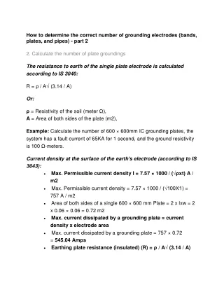
How to determine the correct number of grounding electrodes (bands, plates, and pipes) - part 2 2. Calculate the number of plate groundings The resistance to earth of the single plate electrode is calculated according to IS 3040: R = ρ / A√ (3.14 / A) Or: ρ = Resistivity of the soil (meter Ω), A = Area of both sides of the plate (m2), Example: Calculate the number of 600 × 600mm IC grounding plates, the system has a fault current of 65KA for 1 second, and the ground resistivity is 100 Ω-meters. Current density at the surface of the earth's electrode (according to IS 3043): Max. Permissible current density I = 7.57 × 1000 / (√ρxt) A / m2 Max. Permissible current density = 7.57 × 1000 / (√100X1) = 757 A / m2 Area of both sides of a single 600 × 600 mm Plate = 2 x lxw = 2 x 0.06 × 0.06 = 0.72 m2 Max. current dissipated by a grounding plate = current density x electrode area Max. current dissipated by a grounding plate = 757 × 0.72 = 545.04 Amps Earthing plate resistance (insulated) (R) = ρ / A√ (3.14 / A)
Earthing plate resistance (isolated) (R) = 100 / 0.72x√ (3.14 / .072) = 290.14 Ω Number of required earthing plates = Current Fault / Max. Current dissipated through an earth pipe. Number of required earthing plates = 65000 / 545.04 = 119 No. Total number of grounding plates required = 119 No. Overall resistance of 119 No. of the grounding plate = 290.14 / 119 = 2.438 Ω. 3. Calculation of the resistance of the bare earthing strip 1) Calculation of the resistance to earth of a buried strip (according to IEEE) The resistance to earth of a single strip of rod buried in the ground is: R = ρ / Px3.14xL (box (2xLxL / Wxh) + Q) Or: ρ = Resistivity of the soil (meter Ω), h = Depth of the electrode (meter), w = Width of the strip or diameter of the conductor (meter) L = Length of the strip or of the conductor (meter) P and Q are Coefficients 2) Calculation of the resistance to earth of a buried strip (according to IS 3043) The resistance to earth of a single strip of rod buried in the ground is: R = 100xρ / 2 × 3.14xL (box (2xLxL / Wxt)) Or:
ρ = Soil resistivity (meter Ω), L = Length of strip or conductor (cm) w = Width of strip or conductor diameter (cm) t = Depth of burial (cm) Example: Calculate the earthing resistance of grounding strips/wires 36 mm in diameter, 262 meters long, buried at a depth of 500 mm in the ground, the resistivity of the soil is 65 Ω meters. Here: R = resistance of the ground rod in W. r = Soil resistivity (meter Ω) = 65 Ω meter l = rod length (cm) = 262m = 26200 cm d = internal rod diameter (cm) = 36mm = 3.6cm h = Strip / rod depth buried (cm) = 500mm = 50cm Earth / conductor strip resistance (R) = ρ / 2 × 3.14xL (lodge (2xLxL / Wt)) Earth / conductor strip resistance (R) = 65/2 × 3.14x26200xln (2x26200x26200 / 3.6 × 50) Earth / conductor strip resistance (R) = = 1.7 Ω 4. Calculate Min. Cross-section of the grounding conductor Cross section of the earth conductor according to IS 3043 (A) = (Si x√t) / K Or: t = Current fault time (second). K = Material constant.
Example: Calculate the cross-sectional area ofthe GI earthing conductor of the system with a fault current of 50 kA for 1 second. The corrosion will be 1.0% per year and the number of years for replacement is 20 years. Cross section of the earthing conductor (A) = (Si x√t) / K Here: If = 50,000 amperes T = 1 second K = 80 ( Material constant, for IG = 80, copper K = 205, aluminum K = 126 ). Cross section of earth conductor (A) = (50000 × 1) / 80 Cross-section of GI earthing conductor (A) = 625 Sq.mm Corrosion allowance = 1.0% per year and number of years before replacement, for example, = 20 years Total allowance = 20 x 1.0% = 20% Safety factor = 1.5 Required earthing conductor size = cross section x total tolerance x safety factor Required grounding conductor size = 1125 square feet, or 1200 square feet Therefore, we consider the GI bands 1Nox12x100 mm or 2Nox6 x 100 mm </ p> Rule of thumb for calculating the number of ground stakes The approximate resistance to ground of the rod/pipe electrodes can be calculated as follows: Earth resistance of Rod / Pipe electrodes:
R = K x ρ / L Or: ρ = Resistivity of the earth in Ohm-meter L = Length of the electrode in meters. d = Diameter of the electrode in meters. K = 0.75 if 25 <L / d <100. K = 1 if 100 <L / d <600 K = 1.2 o / L if 600 <L / d <300 Number of electrodes if determined by the equation of R (d) = (1.5 / N) x R Or: R (d) = Desired earthresistance R = Single electrode resistance N = Number of electrodes installed in parallel at a distance of 3 to 4 meters apart. Example: Calculate the resistance of the earthing pipe and the number of electrodes to obtain an earthing resistance of 1 Ω, a soil resistivity of ρ = 40, a length = 2.5 meters, a diameter pipe length = 38 mm. Here: L / d = 2.5 / 0.038 = 65.78 K = 0.75 The resistance to earth of the pipe electrodes R = K x ρ / L = 0.75 × 65.78 = 12 Ω An electrode resistance to earth is 12 Ω . To obtain a resistance to earth of 1 Ω, the total number of electrodes needed = (1.5 × 12) / 1 = 18 no
Calculation of resistance and number of grounding rods Reference: According to the Reference Book for EHV Transmission Lines page: 290 and the Westinghouse Electric Corporation Power Transmission and Distribution Reference Book, Section-I page: 570-590. Earth resistance of single rods: R = ρx [ln (2L / a) -1] / (2 × 3.14xL) Earth resistance of parallel rods: R = ρx [ln (2L / A] / (2 × 3.14xL) Or: L = length of rod in soil meter, a = radius of rod meter ρ = resistivity of earth, ohmmeter A = √ (axS) S = rod separation meter Earth stake arrangements The factor affects the ground resistance The NEC code requires the minimum length of the earth electrode to be 2.5 meters (8.0 feet) to be in contact with the ground. However, some factors affect the resistance to earth of a ground system: Length / Depth of the earth electrode: double the length, reduce the resistance to earth by up to 40%. Earth electrode diameter: doubles the diameter, reducing ground resistance by only 10%.
A number of Ground Electrodes : For increased efficiency, space additional electrodes at least equal to the depth of the ground electrodes. Ground system design : single ground rod to the ground plate. GI earth conductor sizes for various equipment No Equipment Earth strip size Equipment, structures, cable trays and HV fence, rails, gate and column in HV steel 1 55 x 6 mm (GI) 25 X 3 mm (Copper) 2 Arrestor lighting 25 X 3 mm (Copper) 3 PLC panel 50X6 mm (Copper) 4 DG and neutral transformer 5 Transformer body 50 × 6 mm (GI) 6 Control panel and relay 25 x 6 mm (GI) 7 Lighting panel and local panel 25 x 6 mm (GI) 8 Distribution board 25 x 6 mm (GI) 9 Motor up to 5.5 kW 4 mm2 (GI) 10 Motor from 5.5 kW to 55 kW 25 x 6 mm (GI) 11 Motor 22 kW to 55 kW 40 x 6 mm (GI) 12 Motor greater than 55 kW 55 x 6 mm (GI)
Selecting the earthing system: IR value required Earth system Capacity Installations / Isc Soil type / resistivity Normal earth / up to 50 ohm-meter Single electrode Sandy soil / between 50 and 2000 ohm- meter Single electrode Rocky ground / More than 2000 ohmmeters Several electrodes Earth connection / 3kA 8 ohms Normal earth / up to 50 ohm-meter Single electrode Sandy soil / between 50 and 2000 ohm- meter Several electrodes Rocky ground / More than 2000 ohmmeters Commercial space, office / 5kA Several electrodes 2 ohms Normal earth / up to 50 ohm-meter Single electrode Substation Earth Transformers, LT / 15kA Line Equipment Sandy soil / between 50 and 2000 ohm- meter less than 1 ohm Several electrodes
Rocky ground / More than 2000 ohmmeters Several electrodes Normal earth / up to 50 ohm-meter Single electrode Sandy soil / between 50 and 2000 ohm- meter Several electrodes Rocky ground / More than 2000 ohmmeters LA, high current equipment / 50kA less than 1 ohm Several electrodes Normal earth / up to 50 ohm-meter Single electrode Sandy soil / between 50 and 2000 ohm- meter Several electrodes Rocky ground / More than 2000 ohmmeters PRS, UTS, RTU, data center, etc./5KA less than 0.5 ohm Several electrodes Earth conductor size Ref IS 3043 and BS 7671 manual: The Lee Wiring Regulations by Trevor E. Marks. Earth conductor size Zone of the earth conductor (mm2) when it is the same material as the phase conductor Earth conductor area (mm2) when it is not the same material as the phase conductor Area of phase conductor S (mm2)
S <16 mm2 S SX (k1 / k2) 16 mm2 <S <35 mm2 16 mm2 16X (k1 / k2) S> 35 mm2 S / 2 SX (k1 / 2k2) K1 is the value of the phase conductor, k2 is the value of the earth conductor K value for IG = 80, Alu = 126, Cu = 205 for 1 second Standard earth strip / plate / pipe / wire weight GI grounding strip: Size (mm2) Weight 20 x 3 500 g per meter 25 x 3 600 g per meter 25 x 6 1/200 Kg per meter 32 x 6 1/600 Kg per meter 40 x 6 2 kg per meter 50 x 6 2/400 kg per meter 65 x 10 5/200 Kg per meter 75 x 12 7/200 Kg per meter GI ground plate plate Weight 600 x 600 x 3 mm 10 kg app.
600 x 600 x 4 mm 12 Kg App. 600 x 600 x 5 mm 15 Kg App. 600 x 600 x 6 mm 18 Kg App. 600 x 600 x 12 mm 36 kg app. 1200 x 1200 x 6 mm 70 Kg App. 1200 x 1200 x 12 mm 140 Kg App. GI ground pipe Pipe Weight 3 meters long BISE 5 kg app. 3 meters r Long BISE 9 kg app. 4.5 meters (15 'Long BISE) 5 kg app. 4.5 meters (15 'Long BISE) 9 kg app. 4.5 meters (15 'Long BISE) App 14 Kg GI ground wire plate Weight 6 swg 5 meters in 1 kg 8 swg 9 meters in 1 kg BurraqEngineering Solutions is the best training institute in Lahore which is providing practical training of Electrical Automation and Short Electrical
Courses including PLC course, SOLAR SYSTEM Installation and DESIGN COURSE, ETAP course, DIALUX course, Panel FABRICATION course, VFD course, ADVANCED control Panel, SWITCHERGEAR design course, Building Electrical design course and all electrical diploma courses. Both online and physical classes available. We introduce a platform Lyskills from where you can get lifetime access to your desire courses at a very reasonable price.