Circuit breakers classified by interruption medium
40 likes | 57 Views
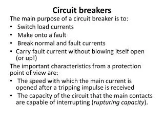
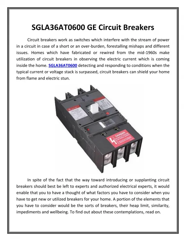
A circuit breaker is defined as u201ca mechanical switching device capable of creating, supporting and breaking currents under normal circuit conditions as well as generating, withstanding and breaking for a specified time, as well as breaking currents under normal circuit conditions. specified abnormal circuit conditions, such as short circuit u201d(IEEE C37.100 Standard).<br><br>

Circuit breakers classified by interruption medium
E N D
Presentation Transcript
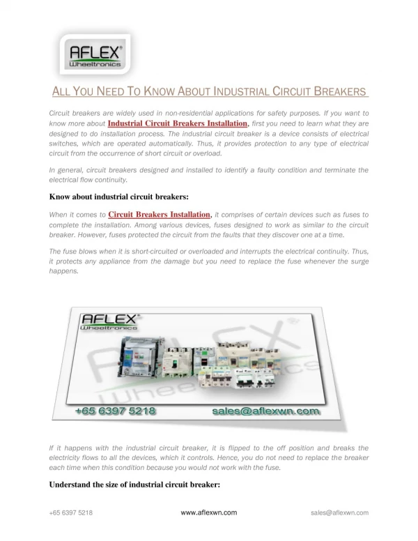
Circuit breakers classified by interruption medium A circuit breaker is defined as “a mechanical switching device capable of creating, supporting and breaking currents under normal circuit conditions as well as generating, withstanding and breaking for a specified time, as well as breaking currents under normal circuit conditions. specified abnormal circuit conditions, such as short circuit ”(IEEE C37.100 Standard). Circuit breakers are generally classified according to the interrupting medium used to cool and lengthen the electric arc, which allows an interruption. The types of circuit breakers are: • Magnetic air • Oil • air blast • vacuum • SF6 gas Magnetic air circuit breakers are limited to old switchgear and have generally been replaced by vacuum or SF6 for switchgear applications. Vacuum is used for switching applications and some outdoor circuit breakers, typically less than 38 kV class. Compressed air circuit breakers, used for high voltages (≥ 765 kV), are no longer manufactured and have been replaced by circuit breakers using SF6 technology. Oil circuit breakers have been widely used in the past utility industry, but have been replaced by other circuit breaker technologies for newer installations. Two models exist bulk oil (dead tank models) dominant in the United States; and minimum oil breaker technology (live tank design). Bulk oil circuit breakers were designed as single-tank or three-tank mechanisms; generally, at higher voltages, three-tank designs were dominant. Oil circuit breakers were bulky and required a significant foundation to support the weight and loads due to operation. To get more training related to engineering click the link. Environmental concerns forcing the need for oil retention systems, maintenance costs and the development of the SF6 gas circuit breaker have led to the gradual replacement of the oil circuit breaker for new installations. The development of oil circuit breakers has been relatively static for many years. The switch design uses the arc created when the contacts are separated and the circuit breaker begins to operate. The electric arc generates hydrogen under the effect of the decomposition of the insulating mineral oil. The switch is designed to use gas as a
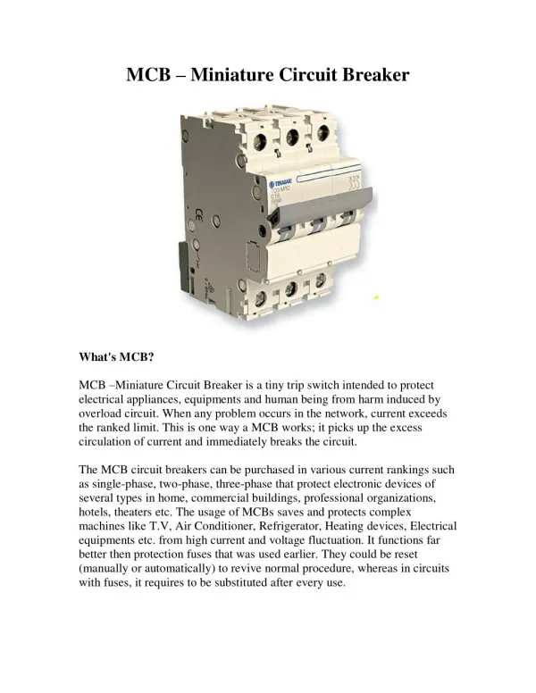
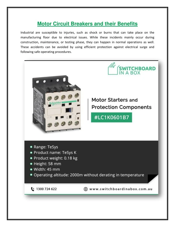
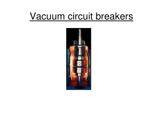
cooling mechanism to cool the arc and to use pressure to lengthen the arc through a grid (arc cuts), allowing the arc to be extinguished when the current goes to zero. Vacuum circuit breakers use a switch which is a small cylinder enclosing the movable high vacuum contacts. When the contacts separate, an arc forms from the erosion of the contacts. The arcing products are immediately forced and deposited on a metal shield surrounding the contacts. With nothing to support the arc, it quickly extinguishes. Vacuum circuit breakers are widely used for shielded switchgear up to 38 kV. The small size of the circuit breaker allows for vertically stacked installation of circuit breakers in a two-height configuration in a vertical section of the switchgear, resulting in considerable space and material savings over previous designs using the technology. air- magnetic. When used in outdoor circuit breaker designs, the vacuum cylinder is housed in a metal cabinet or oil filled tank for dead tank construction popular in the US market. Each circuit breaker is made up of three puffer-type SF6 switches, offering a high level of insulation, excellent breaking capacity and a spring-operated operating mechanism ensuring high operating reliability. circuit breaker Gas circuit breakers generally use SF6 (sulfurhexafluoride) as an interrupting medium and sometimes as an insulator. In “single blow” mechanisms, the switch is designed to
compress the gas during the opening stroke and use the compressed gas as a transfer mechanism to cool the arc and lengthen the arc through a grid (chutes). ‘arc), allowing the arc to be extinguished when the current passes through zero. In other designs, the arc heats the SF6 gas and the resulting pressure is used to lengthen and interrupt the arc. Some older two-pressure SF6 circuit breakers used a pump to supply the high pressure SF6 gas for arc interruption. Gas circuit breakers typically operate at pressures between six and seven atmospheres. The dielectric strength of SF6 gas decreases considerably at lower pressures, normally due to lower ambient temperatures. Monitoring the density of SF6 gas is essential and some designs will block circuit breaker operation in low gas density conditions. Circuit breakers are available as livewell or dead tank designs. Dead tank designs put the switch in a grounded metal case. The switches are maintained at ground level and the seismic resistance is improved compared to the live tank models. Bushings are used for line and load connections, allowing the installation of feedthrough current transformers for relay and metering at nominal cost The dead tank circuit breaker requires additional insulating oil or gas to provide insulation between the switch and the grounded tank enclosure. Live tank circuit breakers consist of an interrupting chamber mounted on insulators and with line potential. This approach allows for a modular design since the switches can be connected in series to operate at higher voltage levels. Contacts are typically actuated by an insulated control rod or by the rotation of a porcelain insulator by an operator at ground level. This design minimizes the amount of oil or gas used to interrupt the arc, with no additional amount required for dead enclosure insulation. The design also easily accommodates adding pre-insertion resistors or leveling capacitors as needed. Interruption times are usually given in cycles and are defined as the maximum possible time between energizing the trip circuit at rated control voltage and interrupting the main contacts on all poles. This applies to all currents between 25 and 100% of the rated short-circuit current. The characteristics of circuit breakers should be carefully considered. The nominal voltage and cut-off values are given at a maximum nominal voltage, i.e. a nominal voltage of 38 kV for a circuit breaker applied on a nominal circuit of 34.5 kV. Circuit breakers have an operating range designated as K Factor according to IEEE C37.06. For a 72 kV circuit breaker, the voltage range is 1.21, indicating that the circuit breaker is capable of operating at its full interruption up to a voltage of 60 kV. Circuit breaker ratings should be verified for specific applications. Applications requiring reclosing
operation should be examined to ensure that the duty cycle of the circuit breaker is not exceeded. Certain applications for out-of-phase switching or back-to-back switching of capacitor banks should also be reviewed and may require special-purpose circuit breakers to ensure proper circuit breaker operation during a fault interruption.