Download

1 / 76

E N D
W HITE PAPER Understanding IPAddressing: Everything You Ever Wanted To Know
Understanding IP Addressing: Everything You Ever Wanted T o Know CONTENTS Internet Scaling Problems 1 Classful IP Addressing 3 Subnetting 7 Variable Length Subnet Masks (VLSM) 18 Classless Inter-Domain Routing (CIDR) 31 New Solutions for Scaling the Internet Address Space 39 IPv6 Resolves IPv4 Issues 42 Additional IPv6 Features 49 Keeping Current on Internet Addressing Issues 50 Appendix A - References 52 Appendix B - Classful IP Addressing 55 Appendix C - Subnetting Exercises 57 Appendix D - VLSM Exercise 61 Appendix E - CIDR Exercises 66 III
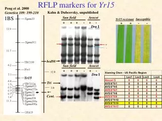
Understanding IP Addressing: Everything You Ever Wanted To Know The Internet continues to grow at a phenomenal rate. This is reflected in the tremendous popularity of the World Wide Web (WWW), the opportu- nities that businesses see in reaching customers from virtual storefronts, and the emergence of new ways of doing business. It is clear that expanding business and public awareness will continue to increase demand for access to resources on the Internet. Internet Scaling Problems Over the past few years, the Internet has experienced two major scaling issues as it has struggled to provide continuous and uninterrupted growth: • The eventual exhaustion of IP version 4 (IPv4) address space • The need to route traffic between the ever increasing number of net- works that comprise the Internet The first problem is concerned with the eventual depletion of the IP address space. IPv4 defines a 32-bit address which means that there are only 232 (4,294,967,296) IPv4 addresses available. As the Internet con- tinues to grow, this finite number of IP addresses will eventually be exhausted. The address shortage problem is aggravated by the fact that portions of the IP address space have not been efficiently allocated. Also, the tradi- tional model of classful addressing does not allow the address space to be used to its maximum potential. The Address Lifetime Expectancy (ALE) Working Group of the Internet Engineering Task Force (IETF) has expressed concerns that if the current address allocation policies are not modified, the Internet will experience a near to medium term exhaus- tion of its unallocated address pool. If the Internet’s address supply problem is not solved, new users may be unable to connect to the global Internet. More than half of all possible IPv4 addresses have been assigned to ISPs, corporations, and government agencies, but only an estimated 69 million addresses are actually in use. FIGURE 1. Net w ork Number Grow t h 1
The second problem is caused by the rapid growth in the size of the Internet routing tables. Internet backbone routers are required to main- tain complete routing information for the Internet. Over recent years, routing tables have experienced exponential growth as increasing num- bers of organizations connect to the Internet. In December 1990 there were 2,190 routes, in December 1995 there were more than 30,000 routes, and in December 2000 more than 100,000 routes. FIGURE 2. Grow t h of Int ernet Rout ing Tables Unfortunately, the routing problem cannot be solved by simply installing more router memory and increasing the size of the routing tables. Other factors related to the capacity problem include the grow- ing demand for CPU horsepower to compute routing table/topology changes, the increasingly dynamic nature of WWW connections and their effect on router forwarding caches, and the sheer volume of infor- mation that needs to be managed by people and machines. If the num- ber of entries in the global routing table is allowed to increase without bounds, core routers will be forced to drop routes and portions of the Internet will become unreachable. The long-term solution to these problems can be found in the wide- spread deployment of IP Next Generation (IPng or IPv6). Currently, IPv6 is being tested and implemented on the 6Bone network, which is an informal collaborative project covering North America, Europe, and Japan. 6Bone supports the routing of IPv6 packets, since that function has not yet been integrated into many production routers. Until IPv6 can be deployed worldwide, IPv4 patches will need to be used and modified to continue to provide the universal connectivity users have come to expect. UNDERSTANDING IP ADDRESSING 2
Classful IP Addressing When IP was first standardized in September 1981, the specification required that each system attached to an IP-based Internet be assigned a unique, 32-bit Internet address value. Systems that have interfaces to more than one network require a unique IP address for each network interface. The first part of an Internet address identifies the network on which the host resides, while the second part identifies the particular host on the given network. This creates the two-level addressing hierar- chy that is illustrated in Figure 3. FIGURE 3. Tw o-Level Int ernet Address St ruct ure In recent years, the network number field has been referred to as the network prefix because the leading portion of each IP address identifies the network number. All hosts on a given network share the same net- work prefix but must have a unique host number. Similarly, any two hosts on different networks must have different network prefixes but may have the same host number. Primary Address Classes To provide the flexibility required to support networks of varying sizes, the Internet designers decided that the IP address space should be divided into three address classes-Class A, Class B, and Class C. This is often referred to as classful addressing. Each class fixes the boundary between the network prefix and the host number at a different point within the 32-bit address. The formats of the fundamental address classes are illustrated in Figure 4. FIGURE 4. Principle Classf ul IP Address Formats 3
One of the fundamental features of classful IP addressing is that each address contains a self-encoding key that identifies the dividing point between the network prefix and the host number. For example, if the first two bits of an IP address are 1-0, the dividing point falls between the 15th and 16th bits. This simplified the routing system during the early years of the Internet because the original routing protocols did not supply a deciphering key or mask with each route to identify the length of the network prefix. Class A Networks (/8 Prefixes) Each Class A network address has an 8-bit network prefix, with the highest order bit set to 0 (zero) and a 7-bit network number, followed by a 24-bit host number. Today, Class A networks are referred to as “/8s” (pronounced “slash eight” or just “eights”) since they have an 8- bit network prefix. A maximum of 126 (27 -2) /8 networks can be defined. The calculation subtracts two because the /8 network 0.0.0.0 is reserved for use as the default route and the /8 network 127.0.0.0 (also written 127/8 or 127.0.0.0/8) is reserved for the “loopback” function. Each /8 supports a maximum of 224 -2 (16,777,214) hosts per network. The host calculation subtracts two because the all-0s (all zeros or “this network”) and all-1s (all ones or “broadcast”) host numbers may not be assigned to individual hosts. Since the /8 address block contains 231 (2,147,483,648 ) individual addresses and the IPv4 address space contains a maximum of 232 (4,294,967,296) addresses, the /8 address space is 50 percent of the total IPv4 unicast address space. Class B Networks (/16 Prefixes) Each Class B network address has a 16-bit network prefix, with the two highest order bits set to 1-0 and a 14-bit network number, followed by a 16-bit host number. Class B networks are now referred to as “/16s” since they have a 16-bit network prefix. A maximum of 16,384 (214 ) /16 networks can be defined with up to 65,534 (216-2) hosts per network. Since the entire /16 address block contains 230 (1,073,741,824) addresses, it represents 25 percent of the total IPv4 unicast address space. Class C Networks (/24 Prefixes) Each Class C network address has a 24-bit network prefix, with the three highest order bits set to 1-1-0 and a 21-bit network number, fol- lowed by an 8-bit host number. Class C networks are now referred to as “/24s” since they have a 24-bit network prefix. A maximum of 2,097,152 (221 ) /24 networks can be defined with up to 254 (28-2) hosts per network. Since the entire /24 address block con- tains 229 (536,870,912) addresses, it represents 12.5 percent (or one- eighth) of the total IPv4 unicast address space. UNDERSTANDING IP ADDRESSING 4
Other Classes In addition to the three most popular classes, there are two additional classes. Class D addresses have their leading four bits set to 1-1-1-0 and are used to support IP Multicasting. Class E addresses have their leading four bits set to 1-1-1-1 and are reserved for experimental use. Dotted-Decimal Notation To make Internet addresses easier for people to read and write, IP addresses are often expressed as four decimal numbers, each separated by a dot. This format is called “dotted-decimal notation.” Dotted-decimal notation divides the 32-bit Internet address into four 8- bit fields and specifies the value of each field independently as a deci- mal number with the fields separated by dots. Figure 5 shows how a typical /16 (Class B) Internet address can be expressed in dotted-decimal notation. FIGURE 5. Dot t ed Decimal Not at ion Table 1 displays the range of dotted-decimal values that can be assigned to each of the three principle address classes. The “xxx” represents the host number field of the address that is assigned by the local network administrator. TABLE 1. Dot t ed Decimal Ranges f or Each Address Class 5
Unforeseen Limitations to Classful Addressing The original Internet designers never envisioned that the Internet would grow into what it has become today. Many of the problems that the Internet is facing today can be traced back to the early decisions that were made during its formative years. • During the early days of the Internet, the seemingly unlimited address space allowed IP addresses to be allocated to an organization based on its request rather than its actual need. As a result, addresses were freely assigned to those who asked for them without concerns about the eventual depletion of the IP address space. • The decision to standardize on a 32-bit address space meant that there were only 232 (4,294,967,296) IPv4 addresses available. A decision to support a slightly larger address space would have exponentially increased the number of addresses thus eliminating the current address shortage problem. • The classful A, B, and C octet boundaries were easy to understand and implement, but they did not foster the efficient allocation of a finite address space. Problems resulted from the lack of a network class that was designed to support medium-sized organizations. For example, a /24, which supports 254 hosts, is too small while a /16, which supports 65,534 hosts, is too large. In the past, sites with sev- eral hundred hosts were assigned a single /16 address instead of two /24 addresses. This resulted in a premature depletion of the /16 net- work address space. Now the only readily available addresses for medium-sized organizations are /24s, which have the potentially nega- tive impact of increasing the size of the global Internet’s routing table. Figure 6 shows basic class A, B, and C networks. UNDERSTANDING IP ADDRESSING 6
The subsequent history of Internet addressing involved a series of steps that overcame these addressing issues and supported the growth of the global Internet. FIGURE 6. Basic Class A, B, and C Net w orks Additional Practice with Classful Addressing Appendix B provides exercises using Classful IP Addressing. 7
Subnetting In 1985, RFC 950 defined a standard procedure to support the subnet- ting, or division, of a single Class A, B, or C network number into smaller pieces. Subnetting was introduced to overcome some of the problems that parts of the Internet were beginning to experience with the classful two-level addressing hierarchy, such as: • Internet routing tables were beginning to grow. • Local administrators had to request another network number from the Internet before a new network could be installed at their site. Both of these problems were attacked by adding another level of hierar- chy to the IP addressing structure. Instead of the classful two-level hier- archy, subnetting supports a three-level hierarchy. Figure 7 illustrates the basic idea of subnetting, which is to divide the standard classful host number field into two parts-the subnet number and the host num- ber on that subnet. FIGURE 7. Subnet Address Hierarchy Subnetting attacked the expanding routing table problem by ensuring that the subnet structure of a network is never visible outside of the organization’s private network. The route from the Internet to any sub- net of a given IP address is the same, no matter which subnet the desti- nation host is on. This is because all subnets of a given network number use the same network prefix but different subnet numbers. The routers within the private organization need to differentiate between the indi- vidual subnets, but as far as the Internet routers are concerned, all of the subnets in the organization are collected into a single routing table entry. This allows the local administrator to introduce arbitrary com- plexity into the private network without affecting the size of the Inter- net’s routing tables. Subnetting overcame the registered number issue by assigning each organization one (or at most a few) network numbers from the IPv4 address space. The organization was then free to assign a distinct sub- network number for each of its internal networks. This allowed the organization to deploy additional subnets without obtaining a new net- work number from the Internet. UNDERSTANDING IP ADDRESSING 8
FIGURE 8. Subnet t ing t he Rout ing Requirement s of t he Int ernet In Figure 8, a site with several logical networks uses subnet addressing with a single /16 (Class B) network address. The router accepts all traffic from the Internet addressed to network 130.5.0.0, and forwards traffic to the interior subnetworks based on the third octet of the classful address. The deployment of subnetting within the private network pro- vides several benefits: • The size of the global Internet routing table does not grow because the site administrator does not need to obtain additional address space and the routing advertisements for all of the subnets are combined into a single routing table entry. • The local administrator has the flexibility to deploy additional sub- nets without obtaining a new network number from the Internet. • Route flapping (that is, the rapid changing of routes) within the pri- vate network does not affect the Internet routing table since Internet routers do not know about the reachability of the individual subnets- they just know about the reachability of the parent network number. Extended Network Prefix Internet routers use only the network prefix of the destination address to route traffic to a subnetted environment. Routers within the subnet- ted environment use the extended network prefix to route traffic between the individual subnets. The extended network prefix is com- posed of the classful network prefix and the subnet number. FIGURE 9. Ext ended Net w ork Pref ix 9
The extended network prefix has traditionally been identified by the subnet mask. For example, if an administrator has the /16 address of 130.5.0.0 and wants to use the entire third octet to represent the subnet number, the administrator must specify a subnet mask of 255.255.255.0. The bits in the subnet mask and the Internet address have a one to one correspondence. The bits of the subnet mask are set to 1 (one) if the sys- tem examining the address should treat the corresponding bit in the IP address as part of the extended network prefix. The bits in the mask are set to 0 (zero) if the system should treat the bit as part of the host num- ber. This numbering is illustrated in Figure 10. FIGURE 10. Subnet M ask The standards describing modern routing protocols often refer to the extended network prefix length rather than the subnet mask. The pre- fix length is equal to the number of contiguous one-bits in the tradi- tional subnet mask. This means that specifying the network address 130.5.5.25 with a subnet mask of 255.255.255.0 can also be expressed as 130.5.5.25/24. The /<prefix length> notation is more compact and eas- ier to understand than writing out the mask in its traditional dotted- decimal format. This is illustrated in Figure 11. FIGURE 11. Ext ended Net w ork Pref ix Lengt h Note that modern routing protocols still carry the subnet mask. None of the Internet standard routing protocols have a 1-byte field in the header that contains the number of bits in the extended network prefix. Each routing protocol is still required to carry the complete four-octet subnet mask. UNDERSTANDING IP ADDRESSING 10
Subnet Design Considerations The deployment of an addressing plan requires careful thought. Four key questions that must be answered before any design should be undertaken are: 1 How many total subnets does the organization need today? 2 How many total subnets will the organization need in the future? 3 How many hosts are on the organization’s largest subnet today? 4 How many hosts will there be on the organization’s largest subnet in the future? The first step in the planning process is to take the maximum number of subnets required and round up to the nearest power of two. For exam- ple, if an organization needs nine subnets, 23 (or 8) will not provide enough subnet addressing space, so the network administrator will need to round up to 24 (or 16). The network administrator must always allow adequate room for growth. For example, although 14 subnets are required today, 16 sub- nets might not be enough in two years when the 17th subnet needs to be deployed. In this case, it would be wise to select 25 (or 32) as the maximum number of subnets. The second step is to ensure that there are enough host addresses for the organization’s largest subnet. If the largest subnet needs to support 50 host addresses today, 25 (or 32) will not provide enough host address space so the network administrator will need to round up to 26 (or 64). The final step is to make sure that the organization’s address allocation provides enough bits to deploy the required subnet addressing plan. For example, if the organization has a single /16, it could easily deploy 4 bits for the subnet number and 6 bits for the host number. However, if the organization has several /24s and it needs to deploy nine subnets, it may have to subnet each of its /24s into four subnets (using 2 bits) and then build the network by combining the subnets of three /24 network numbers. An alternative solution would be to deploy network numbers from the private address space (RFC 1918) for internal connectivity and use a Network Address Translator (NAT) to provide external Internet access. Subnet Example #1 Given An organization is assigned the network number 193.1.1.0/24 and it needs to define six subnets. The largest subnet is required to support 25 hosts. 11
Defining the Subnet Mask / Extended Prefix Length The first step in defining the subnet mask is to determine the number of bits required to define the six subnets. Since a network address can only be subnetted along binary boundaries, subnets must be created in blocks of powers of two [2 (21), 4 (22), 8 (23), 16 (24), and so on]. Thus, it is impossible to define an IP address block such that it contains exactly six subnets. For this example, the network administrator must define a block of 8 (23) and have two unused subnets that can be reserved for future growth. Since 8 = 23, three bits are required to enumerate the eight subnets in the block. In this example, the organization is subnetting a /24 so it will need three more bits, or a /27, as the extended network prefix. A 27-bit extended network prefix can be expressed in dotted-decimal notation as 255.255.255.224. This notation is illustrated in Figure 12. FIGURE 12. Example #1-Def ining t he Subnet M ask/Ext ended Pref ix Lengt h A 27-bit extended network prefix leaves 5 bits to define host addresses on each subnet. This means that each subnetwork with a 27-bit prefix represents a contiguous block of 25 (32) individual IP addresses. How- ever, since the all-0s and all-1s host addresses cannot be allocated, there are 30 (25-2) assignable host addresses on each subnet. Defining the Subnet Numbers The eight subnets will be numbered 0 through 7. Throughout the remainder of this paper, the XXX notation indicates the binary repre- sentation of the number. The 3-bit binary representation of the decimal values 0 through 7 are: 0 (000 ), 1 (001 ), 2 (010 ), 3 (011 ), 4 (100 ), 5 (101 ), 6 (110 ), and 7 (111 ). In general, to define Subnet #N, the network administrator places the binary representation of N into the bits of the subnet number field. For example, to define Subnet #6, the network administrator simply places the binary representation of 6 (110 ) into the 3 bits of the subnet num- ber field. UNDERSTANDING IP ADDRESSING 12
The eight subnet numbers for this example are listed in the following code sample. The underlined portion of each address identifies the extended network prefix, while the bold digits identify the 3 bits repre- senting the subnet number field: Base Net: 11000001.00000001.00000001 .00000000 = 193.1.1.0/24 Subnet #0: 11000001.00000001.00000001.000 00000 = 193.1.1.0/27 Subnet #1: 11000001.00000001.00000001.001 00000 = 193.1.1.32/27 Subnet #2: 11000001.00000001.00000001.010 00000 = 193.1.1.64/27 Subnet #3: 11000001.00000001.00000001.011 00000 = 193.1.1.96/27 Subnet #4: 11000001.00000001.00000001.100 00000 = 193.1.1.128/27 Subnet #5: 11000001.00000001.00000001.101 00000 = 193.1.1.160/27 Subnet #6: 11000001.00000001.00000001.110 00000 = 193.1.1.192/27 Subnet #7: 11000001.00000001.00000001.111 00000 = 193.1.1.224/27 An easy way to verify that the subnets are correct is to ensure that they are all multiples of the Subnet #1 address. In this example, all subnets are multiples of 32: 0, 32, 64, 96, and so on. The All-0s Subnet and All-1s Subnet When subnetting was first defined in RFC 950, it prohibited the use of the all-0s and the all-1s subnets. The reason for this restriction was to eliminate situations that could potentially confuse a classful router. Today a router can be both classless and classful at the same time-it could be running RIP-1 (classful protocol) and BGP-4 (Border Gateway Protocol Version 4-a classless protocol) at the same time. With respect to the all-0s subnet, a router requires that each routing table update include the route/<prefix length> pair to differentiate between a route to the all-0s subnet and a route to the entire network. For example, when using RIP-1which does not supply a mask or prefix length with each route, the routing advertisements for subnet 193.1.1.0/27 and for network 193.1.1.0/24 are identical-193.1.1.0. With- out somehow knowing the prefix length or mask, a router cannot tell the difference between a route to the all-0s subnet and the route to the entire network. This example is illustrated in Figure 13. FIGURE 13. Diff erent iat ing Bet w een a Rout e t o t he All-0s Subnet and t he Ent ire Net w ork 13
Regarding the all-1s subnet, a router requires that each routing table entry include the prefix length so that it can determine whether a broadcast (directed or all-subnets) should be sent only to the all-1s sub- net or to the entire network. For example, when the routing table does not contain a mask or prefix length for each route, confusion can occur because the same broadcast address (193.1.1.255) is used for both the entire network 193.1.1.0/24 and the all-1s subnet 193.1.1.224/27. This issue is illustrated in Figure 14. FIGURE 14. Ident if ying a Broadcast t o t he All 1s Subnet and t he Ent ire Net w ork Defining Host Addresses for Each Subnet According to Internet practices, the host number field of an IP address cannot contain all 0-bits or all 1-bits. The all-0s host number identifies the base network (or subnetwork) number, while the all-1s host number represents the broadcast address for the network (or subnetwork). In our current example, there are 5 bits in the host number field of each subnet address. This means that each subnet represents a block of 30 host addresses (25 -2 = 30, note that the 2 is subtracted because the all-0s and the all-1s host addresses cannot be used). The hosts on each subnet are numbered 1 through 30. In general, to define the address assigned to Host #N of a particular subnet, the network administrator places the binary representation of N into the subnet’s host number field. For example, to define the address assigned to Host #15 on Subnet #2, the network administrator simply places the binary representation of 15 (011112 ) into the 5-bits of Sub- net #2’s host number field. UNDERSTANDING IP ADDRESSING 14
The valid host addresses for Subnet #2 in this example are listed in the following sample code. The underlined portion of each address identi- fies the extended network prefix, while the bold digits identify the 5- bit host number field: Subnet #2: 11000001.00000001.00000001.010 00000 = 193.1.1.64/27 Host #1: 11000001.00000001.00000001.010 00001 = 193.1.1.65/27 Host #2: 11000001.00000001.00000001.010 00010 = 193.1.1.66/27 Host #3: 11000001.00000001.00000001.010 00011 = 193.1.1.67/27 Host #4: 11000001.00000001.00000001.010 00100 = 193.1.1.68/27 Host #5: 11000001.00000001.00000001.010 00101 = 193.1.1.69/27 . . Host #15: 11000001.00000001.00000001.010 01111 = 193.1.1.79/27 Host #16: 11000001.00000001.00000001.010 10000 = 193.1.1.80/27 . . Host #27: 11000001.00000001.00000001.010 11011 = 193.1.1.91/27 Host #28: 11000001.00000001.00000001.010 11100 = 193.1.1.92/27 Host #29: 11000001.00000001.00000001.010 11101 = 193.1.1.93/27 Host #30: 11000001.00000001.00000001.010 11110 = 193.1.1.94/27 The valid host addresses for Subnet #6 are listed in the following sam- ple code. The underlined portion of each address identifies the extended network prefix, while the bold digits identify the 5-bit host number field: Subnet #6: 11000001.00000001.00000001.110 00000 = 193.1.1.192/27 Host #1: 11000001.00000001.00000001.110 00001 = 193.1.1.193/27 Host #2: 11000001.00000001.00000001.110 00010 = 193.1.1.194/27 Host #3: 11000001.00000001.00000001.110 00011 = 193.1.1.195/27 Host #4: 11000001.00000001.00000001.110 00100 = 193.1.1.196/27 Host #5: 11000001.00000001.00000001.110 00101 = 193.1.1.197/27 . . Host #15: 11000001.00000001.00000001.110 01111 = 193.1.1.207/27 Host #16: 11000001.00000001.00000001.110 10000 = 193.1.1.208/27 . . Host #27: 11000001.00000001.00000001.110 11011 = 193.1.1.219/27 Host #28: 11000001.00000001.00000001.110 11100 = 193.1.1.220/27 Host #29: 11000001.00000001.00000001.110 11101 = 193.1.1.221/27 Host #30: 11000001.00000001.00000001.110 11110 = 193.1.1.222/27 Defining the Broadcast Address for Each Subnet The broadcast address for Subnet #2 is the all-1s host address or: 11000001.00000001.00000001.010 11111 = 193.1.1.95 Note that the broadcast address for Subnet #2 is exactly one less than the base address for Subnet #3 (193.1.1.96). This is always the case-the broadcast address for Subnet #n is one less than the base address for Subnet #(n+1). 15
The broadcast address for Subnet #6 is simply the all-1s host address or: 11000001.00000001.00000001.110 11111 = 193.1.1.223 Again, the broadcast address for Subnet #6 is exactly one less than the base address for Subnet #7 (193.1.1.224). Subnet Example #2 Given An organization is assigned the network number 140.25.0.0/16 and it must create a set of subnets that supports up to 60 hosts on each subnet. Defining the Subnet Mask / Extended Prefix Length The first step is to determine the number of bits required to define 60 hosts on each subnet. Since a block of host addresses can only be assigned along binary boundaries, host address blocks can only be cre- ated in powers of two. This means that it is impossible to create a block that contains exactly 60 host addresses. To support 60 hosts, the network administrator must define a minimum address block of 62 (26-2) host addresses. However, this choice would only provide two unused host addresses on each subnet for future growth, which is not likely to support additional growth. The network administrator must define a block of 126 (27-2) host addresses with 66 addresses on each subnet for future growth. A block of 126 host addresses requires 7 bits in the host number field. The next step is to determine the subnet mask/extended prefix length. Since 7 bits of the 32-bit IP address are required for the host number field, the extended prefix must be a /25 (25 = 32-7). A 25-bit extended network prefix can be expressed in dotted-decimal notation as 255.255.255.128. This notation is illustrated in Figure 15. FIGURE 15. Example #2-Def ining t he Subnet M ask/Ext ended Pref ix Lengt h UNDERSTANDING IP ADDRESSING 16
Figure 15 shows that the 25-bit extended prefix assigns 9 bits to the subnet number field. Since 29 = 512, nine bits allow the definition of 512 subnets. Depending on the organization’s requirements, the net- work administrator could have elected to assign additional bits to the host number field (allowing more hosts on each subnet) and reduce the number of bits in the subnet number field (decreasing the total number of subnets that can be defined). Although this example creates a rather large number of subnets, it illus- trates what happens to the dotted- decimal representation of a subnet address when the subnet number bits extend across an octet boundary. Note that the same type of confusion can occur when the host number bits extend across an octet boundary. Defining Each of the Subnet Numbers The 512 subnets will be numbered 0 through 511. The 9-bit binary rep- resentation of the decimal values 0 through 511 are: 0 (0000000002 ), 1 (0000000012 ), 2 (0000000102 ), 3 (0000000112 ), ..., 511 (1111111112 ). To define Subnet #3, the network administrator places the binary rep- resentation of 3 (0000000112 ) into the 9 bits of the subnet number field. The 512 subnet numbers for this example are listed in the follow- ing sample code. The underlined portion of each address identifies the extended network prefix, while the bold digits identify the 9 bits repre- senting the subnet number field: Base Net: 10001100.00011001 .00000000.00000000 = 140.25.0.0/16 Subnet #0: 10001100.00011001.00000000.0 0000000 = 140.25.0.0/25 Subnet #1: 10001100.00011001.00000000.1 0000000 = 140.25.0.128/25 Subnet #2: 10001100.00011001.00000001.0 0000000 = 140.25.1.0/25 Subnet #3: 10001100.00011001.00000001.1 0000000 = 140.25.1.128/25 Subnet #4: 10001100.00011001.00000010.0 0000000 = 140.25.2.0/25 Subnet #5: 10001100.00011001.00000010.1 0000000 = 140.25.2.128/25 Subnet #6: 10001100.00011001.00000011.0 0000000 = 140.25.3.0/25 Subnet #7: 10001100.00011001.00000011.1 0000000 = 140.25.3.128/25 Subnet #8: 10001100.00011001.00000100.0 0000000 = 140.25.4.0/25 Subnet #9: 10001100.00011001.00000100.1 0000000 = 140.25.4.128/25 . . Subnet #510: 10001100.00011001.11111111.0 0000000 = 140.25.255.0/25 Subnet #511: 10001100.00011001.11111111.1 0000000 = 140.25.255.128/25 Note that the sequential subnet numbers are not sequential when expressed in dotted-decimal notation. This can be confusing to people who expect dotted-decimal notation to make IP addressing easier. In this example, the dotted-decimal notation obscures the subnet number- ing scheme. 17
Defining Host Addresses for Each Subnet In this example there are 7 bits in the host number field of each subnet address, which means that each subnet represents a block of 126 host addresses. The hosts on each subnet are numbered 1 through 126. The valid host addresses for Subnet #3 are listed in the following sam- ple code. The underlined portion of each address identifies the extended network prefix, while the bold digits identify the 7-bit host number field: Subnet #3: 10001100.00011001.00000001.1 0000000 = 140.25.1.128/25 Host #1: 10001100.00011001.00000001.1 0000001 = 140.25.1.129/25 Host #2: 10001100.00011001.00000001.1 0000010 = 140.25.1.130/25 Host #3: 10001100.00011001.00000001.1 0000011 = 140.25.1.131/25 Host #4: 10001100.00011001.00000001.1 0000100 = 140.25.1.132/25 Host #5: 10001100.00011001.00000001.1 0000101 = 140.25.1.133/25 Host #6: 10001100.00011001.00000001.1 0000110 = 140.25.1.134/25 . . Host #62: 10001100.00011001.00000001.1 0111110 = 140.25.1.190/25 Host #63: 10001100.00011001.00000001.1 0111111 = 140.25.1.191/25 Host #64: 10001100.00011001.00000001.1 1000000 = 140.25.1.192/25 Host #65: 10001100.00011001.00000001.1 1000001 = 140.25.1.193/25 . . Host #123: 10001100.00011001.00000001.1 1111011 = 140.25.1.251/25 Host #124: 10001100.00011001.00000001.1 1111100 = 140.25.1.252/25 Host #125: 10001100.00011001.00000001.1 1111101 = 140.25.1.253/25 Host #126: 10001100.00011001.00000001.1 1111110 = 140.25.1.254/25 Defining the Broadcast Address for Each Subnet The broadcast address for Subnet #3 is the all-1s host address or: 10001100.00011001.00000001.1 1111111 = 140.25.1.255 The broadcast address for Subnet #3 is exactly one less than the base address for Subnet #4 (140.25.2.0). Additional Practice with Subnetworks Appendix C provides exercises using subnetting. UNDERSTANDING IP ADDRESSING 18
Variable Length Subnet Masks (VLSM) In 1987, RFC 1009 specified how a subnetted network could use more than one subnet mask. When an IP network is assigned more than one subnet mask, it is considered a network with (VLSM) since the extended network prefixes have different lengths. RIP-1 Permits Only a Single Subnet Mask When using RIP-1, subnet masks have to be uniform across the entire network prefix. RIP-1 allows only a single subnet mask to be used within each network number because it does not provide subnet mask information as part of its routing table update messages. In the absence of this information, RIP-1 is forced to make assumptions about the mask that should be applied to any of its learned routes. How does a RIP-1 based router know what mask to apply to a route when it learns a new route from a neighbor? If the router has a subnet of the same network number assigned to a local interface, it assumes that the learned subnetwork was defined using the same mask as the locally configured interface. However, if the router does not have a sub- net of the learned network number assigned to a local interface, the router has to assume that the network is not subnetted and applies the route’s natural classful mask. For example, assume that Port 1 of a router has been assigned the IP address 130.24.13.1/24 and that Port 2 has been assigned the IP address 200.14.13.2/24. If the router learns about network 130.24.36.0 from a neighbor, it applies a /24 mask since Port 1 is configured with another subnet of the 130.24.0.0 network. However, when the router learns about network 131.25.0.0 from a neighbor, it assumes a “natural” /16 mask since no other masking information is available. How does a RIP-1 based router know whether it should include the subnet number bits in a routing table update to a RIP-1 neighbor? A router executing RIP-1 will only advertise the subnet number bits on another port if the update port is configured with a subnet of the same network number. If the update port is configured with a different subnet or network number, the router will only advertise the network portion of the subnet route and zero-out the subnet number field. For example, assume that Port 1 of a router has been assigned the IP address 130.24.13.1/24 and that Port 2 has been assigned the IP address 200.14.13.2/24. Also, assume that the router has learned about network 130.24.36.0 from a neighbor. Since Port 1 is configured with another subnet of the 130.24.0.0 network, the router assumes that network 130.24.36.0 has a /24 subnet mask. When it comes to advertise this route, the router advertises 130.24.36.0 on Port 1, but it only advertises 130.24.0.0 on Port 2. 19
For these reasons, RIP-1 is limited to a single subnet mask for each net- work number. However, there are several advantages to be gained if more than one subnet mask can be assigned to a given IP network num- ber: • Multiple subnet masks permit more efficient use of an organization’s assigned IP address space. • Multiple subnet masks permit route aggregation which can signifi- cantly reduce the amount of routing information at the backbone level within an organization’s routing domain. Efficient Use of Assigned IP Address Space VLSM supports more efficient use of an organization’s assigned IP address space. The earlier limitation of supporting only a single subnet mask across a given network prefix locked the organization into a fixed number of fixed sized subnets. For example, assume that a network administrator configured the 130.5.0.0/16 network with a /22 extended network prefix, as shown in Figure 16. A /16 network with a /22 extended network prefix would permit 64 subnets (26), each of which could support a maximum of 1,022 hosts (210-2). FIGURE 16. 130.5.0/16 w it h a /22 Ext ended Net w ork Pref ix Please refer to Figure 16. This configuration would be suitable if the organization wanted to deploy a number of large subnets, but what about the occasional small subnet containing only 20 or 30 hosts? Since a subnetted network could have only a single mask, the network admin- istrator would still be required to assign the 20 or 30 hosts to a subnet with a 22-bit prefix. This assignment would waste approximately 1,000 IP host addresses for each small subnet deployed. Limiting the associa- tion of a network number with a single mask did not encourage the flexible and efficient use of an organization’s address space. One solu- tion to this problem was to allow a subnetted network to be assigned more than one subnet mask. UNDERSTANDING IP ADDRESSING 20
For example, assume that the network administrator was also allowed to configure the 130.5.0.0/16 network with a /26 extended network prefix, as shown in Figure 17. A /16 network address with a /26 extended net- work prefix would permit 1,024 subnets (210), each of which would support a maximum of 62 hosts (26 -2). The /26 prefix would be ideal for small subnets with less than 60 hosts, while the /22 prefix would be well suited for larger subnets containing up to 1,000 hosts. FIGURE 17. 130.5.0/16 w it h a /26 Ext ended Net w ork Pref ix Route Aggregation VLSM also allows the recursive division of an organization’s address space so that it can be reassembled and aggregated to reduce the amount of routing information at the top level. Conceptually, a network is first divided into subnets, then some of the subnets are divided into sub-subnets, and some of the sub subnets are divided into sub-subnets. This allows the detailed structure of routing information for one subnet group to be hidden from routers in another subnet group. 11.0.0.0./8 11.1.0.0/16 11.2.0.0/16 11.3.0.0/16 11.252.0.0/16 11.253.0.0/16 11.254.0.0/16 11.1.1.0/24 11.1.2.0/24 11.1.253.0/24 11.1.254.0/24 11.253.32.0/19 11.253.64.0/19 11.253.160.0/19 11.253.192.0/19 11.1.253.32/27 11.1.253.64/27 11.1.253.160/27 11.1.253.192/27 21
FIGURE 18. Recursive Division of a Net w ork Pref ix In Figure 18, the 11.0.0.0/8 network is first configured with a /16 extended network prefix. The 11.1.0.0/16 subnet is then configured with a /24 extended network prefix and the 11.253.0.0/16 subnet is configured with a /19 extended network prefix. Note that the recursive process does not require that the same extended network prefix be assigned at each level of the recursion. Also, the recursive subdivision of the organization’s address space can be carried out as far as the net- work administrator needs to take it. FIGURE 19. Rout e Aggregat ion, Reducing Rout ing Table Size UNDERSTANDING IP ADDRESSING 22
Figure 19 illustrates how a planned and thoughtful allocation of VLSM can reduce the size of an organization’s routing tables. Notice how Router D can summarize the six subnets behind it into a single adver- tisement (11.1.253.0/24) and how Router B can aggregate all subnets behind it into a single advertisement (11.1.0.0/16). Likewise, Router C can summarize the six subnets behind it into a single advertisement (11.253.0.0/16). Finally, since the subnet structure is not visible outside of the organization, Router A injects a single route into the global Inter- net’s routing table-11.0.0.0/8 (or 11/8). VLSM Design Considerations When developing a VLSM design, the network designer must recur- sively ask the same set of questions as for a traditional subnet design. The same set of design decisions must be made at each level of the hier- archy: 1 How many total subnets does this level need today? 2 How many total subnets will this level need in the future? 3 How many hosts are on this level’s largest subnet today? 4 How many hosts will be on this level’s largest subnet be in the future? At each level, the design team must ensure that they have enough extra bits to support the required number of subentities in the next levels of recursion. Assume that a network is spread out over a number of sites. For exam- ple, if an organization currently has three campuses, it probably needs 3 bits of subnetting (23 = 8) to allow the addition of more campuses in the future. Now, within each campus, there is likely to be a secondary level of subnetting to identify each building. Finally, within each building, a third level of subnetting might identify each of the individual work- groups. Following this hierarchical model, the top level is determined by the number of campuses, the middle level is based on the number of buildings at each site, and the lowest level is determined by the maxi- mum number of subnets and maximum number of users per subnet in each building. The deployment of a hierarchical subnetting scheme requires careful planning. It is essential that the network designers recursively work their way down through their addressing plan until they get to the bot- tom level. At the bottom level, they must make sure that the leaf sub- nets are large enough to support the required number of hosts. When the addressing plan is deployed, the addresses from each site must be aggregated into a single address block that keeps the backbone routing tables from becoming too large. 23
Requirements for Deploying VLSM The successful deployment of VLSM has three prerequisites: • The routing protocols must carry extended network prefix informa- tion with each route advertisement. • All routers must implement a consistent forwarding algorithm based on the “longest match.” • For route aggregation to occur, addresses must be assigned so that they have topological significance. Routing Protocols Must Carry Extended Network Prefix Lengths Routing protocols, such as OSPF and I-IS-IS, enable the deployment of VLSM by providing the extended network prefix length or mask value along with each route advertisement. This permits each subnetwork to be advertised with its corresponding prefix length or mask. If the rout- ing protocols did not carry prefix information, a router would have to either assume that the locally configured prefix length should be applied, or perform a look-up in a statically configured prefix table that contains all of the required masking information. The first alternative cannot guarantee that the correct prefix is applied, and static tables do not scale since they are difficult to maintain and subject to human error. To deploy VLSM in a complex topology, the administrator must select OSPF or I-IS-IS as the Interior Gateway Protocol (IGP) rather than RIP-1. Note that RIP-2, defined in RFC 1388, improves the RIP protocol by allowing it to carry extended network prefix information. Therefore, RIP-2 supports the deployment of VLSM. Forwarding Algorithm Based on the Longest Match All routers must implement a consistent forwarding algorithm based on the longest match algorithm. The deployment of VLSM means that the set of networks associated with extended network prefixes may mani- fest a subset relationship. A route with a longer extended network pre- fix describes a smaller set of destinations than the same route with a shorter extended network prefix. As a result, a route with a longer extended network prefix is more specific while a route with a shorter extended network prefix is less specific. Routers must use the route with the longest matching extended network prefix (most specific matching route) when forwarding traffic. UNDERSTANDING IP ADDRESSING 24
For example, if a packet’s destination IP address was 11.1.2.5 and there were three network prefixes in the routing table (11.1.2.0/24, 11.1.0.0/16, and 11.0.0.0/8), the router would select the route to 11.1.2.0/24. The 11.1.2.0/24 route would be selected because its prefix has the greatest number of corresponding bits in the Destination IP address of the packet. This concept is illustrated in Figure 20. FIGURE 20. Best M at ch Rout e w it h Longest Pref ix (M ost Specif ic) A very subtle but extremely important issue is that since the destina- tion address matches all three routes, it must be assigned to a host that is attached to the 11.1.2.0/24 subnet. If the 11.1.2.5 address is assigned to a host that is attached to the 11.1.0.0/16 or 11.0.0.0/8 subnet, the routing system will never route traffic to the host since the “longest match algorithm” assumes that the host is part of the 11.1.2.0/24 sub- net. Great care must be taken when assigning host addresses to ensure that every host is reachable. Topologically Significant Address Assignment Since OSPF and I-IS-IS convey the extended network prefix information with each route, the VLSM subnets can be scattered throughout an organization’s topology. However, to support hierarchical routing and reduce the size of an organization’s routing tables, addresses should be assigned so that they are topologically significant. Hierarchical routing requires that addresses be assigned to reflect the actual network topology. This reduces the amount of routing informa- tion by aggregating the set of addresses assigned to a particular region of the topology into a single routing advertisement for the entire set. Hierarchical routing allows this to be done recursively at various points within the hierarchy of the routing topology. If addresses do not have a topological significance, they cannot be aggregated and the size of the routing tables cannot be reduced. 25
VLSM Example Given An organization has been assigned the network number 140.25.0.0/16 and it plans to deploy VLSM. Figure 21 provides a graphic display of the VLSM design for the organization. FIGURE 21. Address St rat egy f or VLSM Example The first step of the subnetting process divides the base network address into 16 equally sized address blocks. Then Subnet #1 is divided into 32 equally sized address blocks and Subnet #14 is divided into 16 equally sized address blocks. Finally, Subnet #14-14 is divided into eight equally sized address blocks. Define the 16 Subnets of 140.25.0.0/16 The first step in the subnetting process divides the base network address into 16 equally sized address blocks, as illustrated in Figure 22. FIGURE 22. Sixt een Subnet s f or 140.25.0.0/16 Since 16 = 24, four bits are required to identify each of the 16 subnets. This means that the organization needs four more bits, or a /20, in the extended network prefix to define the 16 subnets of 140.25.0.0/16. Each of these subnets represents a contiguous block of 212 (or 4,096) network addresses. UNDERSTANDING IP ADDRESSING 26
The 16 subnets of the 140.25.0.0/16 address block are listed in the fol- lowing code sample. The subnets are numbered 0 through 15. The underlined portion of each address identifies the extended network pre- fix, while the bold digits identify the 4 bits representing the subnet number field: Base Network: 10001100.00011001 .00000000.00000000 = 140.25.0.0/16 Subnet #0: 10001100.00011001.0000 0000.00000000 = 140.25.0.0/20 Subnet #1: 10001100.00011001.0001 0000.00000000 = 140.25.16.0/20 Subnet #2: 10001100.00011001.0010 0000.00000000 = 140.25.32.0/20 Subnet #3: 10001100.00011001.0011 0000.00000000 = 140.25.48.0/20 Subnet #4: 10001100.00011001.0100 0000.00000000 = 140.25.64.0/20 : : Subnet #13: 10001100.00011001.1101 0000.00000000 = 140.25.208.0/20 Subnet #14: 10001100.00011001.1110 0000.00000000 = 140.25.224.0/20 Subnet #15: 10001100.00011001.1111 0000.00000000 = 140.25.240.0/20 Define the Host Addresses for Subnet #3 (140.25.48.0/20) Figure 23 shows the host addresses that can be assigned to Subnet #3 (140.25.48.0/20). FIGURE 23. Host Address f or Subnet #3 (140.25.48.0/20) Since the host number field of Subnet #3 contains 12 bits, there are 4,094 valid host addresses (212 -2) in the address block. The hosts are numbered 1 through 4,094. The valid host addresses for Subnet #3 are listed in the following sample code. The underlined portion of each address identifies the extended network prefix, while the bold digits identify the 12-bit host number field: Subnet #3: 10001100.00011001.0011 0000.00000000 = 140.25.48.0/20 Host #1: 10001100.00011001.0011 0000.00000001 = 140.25.48.1/20 Host #2: 10001100.00011001.0011 0000.00000010 = 140.25.48.2/20 Host #3: 10001100.00011001.0011 0000.00000011 = 140.25.48.3/20 : : Host #4093: 10001100.00011001.0011 1111.11111101 = 140.25.63.253/20 Host #4094: 10001100.00011001.0011 1111.11111110 = 140.25.63.254/20 27
The broadcast address for Subnet #3 is the all-1s host address or: 10001100.00011001.0011 1111.11111111 = 140.25.63.255 The broadcast address for Subnet #3 is exactly one less than the base address for Subnet #4 (140.25.64.0). Define the Sub-Subnets for Subnet #14 (140.25.224.0/20) After the base network address is divided into 16 subnets, Subnet #14 is subdivided into 16 equally sized address blocks. This division is illus- trated in Figure 24. FIGURE 24. Sub-Subnet s f or Subnet #14 (140.25.224.0/20) Since 16 = 24, four more bits are required to identify each of the 16 subnets. This means that the organization will need to use a /24 as the extended network prefix length. The 16 subnets of the 140.25.224.0/20 address block are listed in the following sample code. The subnets are numbered 0 through 15. The underlined portion of each sub-subnet address identifies the extended network prefix, while the bold digits identify the 4 bits representing the sub-subnet number field: Subnet #14: 10001100.00011001.1110 0000.00000000 = 140.25.224.0/20 Subnet #14-0: 10001100.00011001.1110 0000 .00000000 = 140.25.224.0/24 Subnet #14-1: 10001100.00011001.1110 0001 .00000000 = 140.25.225.0/24 Subnet #14-2: 10001100.00011001.1110 0010 .00000000 = 140.25.226.0/24 Subnet #14-3: 10001100.00011001.1110 0011 .00000000 = 140.25.227.0/24 Subnet #14-4: 10001100.00011001.1110 0100 .00000000 = 140.25.228.0/24 . . Subnet #14-14: 10001100.00011001.1110 1110 .00000000 = 140.25.238.0/24 Subnet #14-15: 10001100.00011001.1110 1111 .00000000 = 140.25.239.0/24 UNDERSTANDING IP ADDRESSING 28
Define Host Addresses for Subnet #14-3 (140.25.227.0/24) Figure 25 shows the host addresses that can be assigned to Subnet #14- 3 (140.25.227.0/24). FIGURE 25. Host Addresses f or Subnet #14-3 (140.25.227.0/24) Each of the subnets of Subnet #14-3 has 8 bits in the host number field. This means that each subnet represents a block of 254 valid host addresses (28 -2). The hosts are numbered 1 through 254. The valid host addresses for Subnet #14-3 are listed in the following sample code. The underlined portion of each address identifies the extended network prefix, while the bold digits identify the 8-bit host number field: Subnet #14 3: 10001100.00011001.11100011 .00000000 = 140.25.227.0/24 Host #1 10001100.00011001.11100011 .00000001 = 140.25.227.1/24 Host #2 10001100.00011001.11100011 .00000010 = 140.25.227.2/24 Host #3 10001100.00011001.11100011 .00000011 = 140.25.227.3/24 Host #4 10001100.00011001.11100011 .00000100 = 140.25.227.4/24 Host #5 10001100.00011001.11100011 .00000101 = 140.25.227.5/24 . . Host #253 10001100.00011001.11100011 .11111101 = 140.25.227.253/24 Host #254 10001100.00011001.11100011 .11111110 = 140.25.227.254/24 The broadcast address for Subnet #14-3 is the all-1s host address or: 10001100.00011001.11100011. 11111111 = 140.25.227.255 The broadcast address for Subnet #14-3 is exactly one less than the base address for Subnet #14-4 (140.25.228.0). 29
Define the Sub-Subnets for Subnet #14-14 (140.25.238.0/24) After Subnet #14 is divided into 16 subnets, Subnet #14-14 is subdi- vided into eight equally sized address blocks, as shown in Figure 26. FIGURE 26. Sub-Subnet s f or Subnet #14-14 (140.25.238.0/24) Since 8 = 23, three more bits are required to identify each of the eight subnets. This means that the organization will need to use a /27 as the extended network prefix length. The eight subnets of the 140.25.238.0/24 address block are listed in the following sample code. The subnets are numbered 0 through 7. The underlined portion of each sub-subnet address identifies the extended network prefix, while the bold digits identify the 3 bits representing the subnet-number field: Subnet #14-14: 10001100.00011001.11101110 .00000000 = 140.25.238.0/24 Subnet#14-14-0: 10001100.00011001.11101110.000 00000 = 140.25.238.0/27 Subnet#14-14-1: 10001100.00011001.11101110.001 00000 = 140.25.238.32/27 Subnet#14-14-2: 10001100.00011001.11101110.010 00000 = 140.25.238.64/27 Subnet#14-14-3: 10001100.00011001.11101110.011 00000 = 140.25.238.96/27 Subnet#14-14-4: 10001100.00011001.11101110.100 00000 = 140.25.238.128/27 Subnet#14-14-5: 10001100.00011001.11101110.101 00000 = 140.25.238.160/27 Subnet#14-14-6: 10001100.00011001.11101110.110 00000 = 140.25.238.192/27 Subnet#14-14-7: 10001100.00011001.11101110.111 00000 = 140.25.238.224/27 UNDERSTANDING IP ADDRESSING 30
Define Host Addresses for Subnet #14-14-2 (140.25.238.64/27) Figure 27 shows the host addresses that can be assigned to Subnet #14- 14-2 (140.25.238.64/27). FIGURE 27. Host Addresses f or Subnet #14-14-2 (140.25.238.64/27) Each of the subnets of Subnet #14-14 has 5 bits in the host number field. This means that each subnet represents a block of 30 valid host addresses (25 -2). The hosts will be numbered 1 through 30. The valid host addresses for Subnet #14-14-2 are listed in the following sample code. The underlined portion of each address identifies the extended network prefix, while the bold digits identify the 5-bit host number field: Subnet#14-14-2: 10001100.00011001.11101110.010 00000 = 140.25.238.64/27 Host #1 10001100.00011001.11101110.010 00001 = 140.25.238.65/27 Host #2 10001100.00011001.11101110.010 00010 = 140.25.238.66/27 Host #3 10001100.00011001.11101110.010 00011 = 140.25.238.67/27 Host #4 10001100.00011001.11101110.010 00100 = 140.25.238.68/27 Host #5 10001100.00011001.11101110.010 00101 = 140.25.238.69/27 . . Host #29 10001100.00011001.11101110.010 11101 = 140.25.238.93/27 Host #30 10001100.00011001.11101110.010 11110 = 140.25.238.94/27 The broadcast address for Subnet #14-14-2 is the all-1s host address or: 10001100.00011001.11011100.010 11111 = 140.25.238.95 The broadcast address for Subnet #6-14-2 is exactly one less than the base address for Subnet #14-14-3 (140.25.238.96). Additional Practice with VLSM Appendix D provides exercises for using VLSM. 31
Classless Inter-Domain Routing (CIDR) By 1992, the exponential growth of the Internet was raising serious con- cerns among members of the IETF about the ability of the Internet’s routing system to scale and support future growth. These problems were related to: • The near-term exhaustion of the Class B network address space • The rapid growth in the size of the global Internet’s routing tables • The eventual exhaustion of the 32-bit IPv4 address space Throughout the Internet’s growth, the first two problems listed became critical and the response to these immediate challenges was the develop- ment of Classless Inter-Domain Routing (CIDR). The third problem, which is of a more long-term nature, is currently being explored by the IP Next Generation (IPng or IPv6) working group of the IETF. CIDR was officially documented in September 1993 in RFC 1517, 1518, 1519, and 1520. CIDR supports two important features that benefit the global Internet routing system: • CIDR eliminates the traditional concept of Class A, Class B, and Class C network addresses. • CIDR supports route aggregation where a single routing table entry can represent the address space of thousands of traditional classful routes. This allows a single routing table entry to specify how to route traffic to many individual network addresses. Route aggregation helps control the amount of routing information in the Internet’s backbone routers, reduces route flapping (rapid changes in route availability), and eases the local administrative burden of updating external rout- ing information. Without the rapid deployment of CIDR in 1994 and 1995, the Internet routing tables would have in excess of 70,000 classful routes and the Internet would probably not be functioning today. CIDR Promotes the Efficient Allocation of the IPv4 Address Space CIDR eliminates the traditional concept of Class A, Class B, and Class C network addresses and replaces them with the generalized concept of a network prefix. Routers use the network prefix, rather than the first 3 bits of the IP address, to determine the dividing point between the net- work number and the host number. As a result, CIDR supports the deployment of arbitrarily sized networks rather than the standard 8-bit, 16-bit, or 24-bit network numbers associated with classful addressing. In the CIDR model, each piece of routing information is advertised with a bit mask (or prefix length). The prefix length is a way of specifying the number of leftmost contiguous bits in the network portion of each routing table entry. For example, a network with 20 bits of network number and 12 bits of host number would be advertised with a 20-bit prefix length (/20). The IP address advertised with the /20 prefix could UNDERSTANDING IP ADDRESSING 32
be a former Class A, Class B, or Class C address. Routers that support CIDR do not make assumptions based on the first three bits of the address, they rely on the prefix length information provided with the route. In a classless environment, prefixes are viewed as bitwise contiguous blocks of the IP address space. For example, all prefixes with a /20 pre- fix represent the same amount of address space (212 or 4,096 host addresses). Furthermore, a /20 prefix can be assigned to a traditional Class A, Class B, or Class C network number. Figure 28 shows how each of the following /20 blocks represent 4,096 host addresses- 10.23.64.0/20, 130.5.0.0/20, and 200.7.128.0/20. FIGURE 28. Bit w ise Cont iguous Address Blocks Table 3 provides information about the most commonly deployed CIDR address blocks. The table shows that a /15 allocation can also be speci- fied using the traditional dotted-decimal mask notation of 255.254.0.0. Also, a /15 allocation contains a bitwise contiguous block of 128K (131,072) IP addresses that can be classfully interpreted as two Class B networks or 512 Class C networks. TABLE 3. CIDR Address Blocks 33
Host Implications for CIDR Deployment There may be severe host implications when CIDR-based networks are deployed. Since many hosts are classful, their user interface will not permit them to be configured with a mask that is shorter than the nat- ural mask for a traditional classful address. For example, to deploy 200.25.16.0 as a /20 to define a network capable of supporting 4,094 (212 -2) hosts, ensure that the software executing on each end station will allow a traditional Class C (200.25.16.0) to be configured with a 20-bit mask since the natural mask for a Class C net- work is a 24-bit mask. If the host software supports CIDR, shorter masks can be configured. There will be no host problems by deploying the 200.25.16.0/20 (a tra- ditional Class C) allocation as a block of 16 /24s since non-CIDR hosts will interpret their local /24 as a Class C. Likewise, 130.14.0.0/16 (a tra- ditional Class B) could be deployed as a block of 255 /24s since the hosts will interpret the /24s as subnets of a /16. If host software supports the configuration of shorter than expected masks, the network manager has tremendous flexibility in network design and address allocation. Efficient Address Allocation How does CIDR lead to the efficient allocation of the IPv4 address space? In a classful environment, an Internet Service Provider (ISP) can only allocate /8, /16, or /24 addresses. In a CIDR environment, the ISP can carve out a block of its registered address space that specifically meets the needs of each client, provides additional room for growth, and does not waste a scarce resource. Assume that an ISP has been assigned the address block 206.0.64.0/18. This block represents 16,384 (214) IP addresses, which can be inter- preted as 64 /24s. If a client requires 800 host addresses, rather than assigning a Class B address (and wasting approximately 64,700 addresses) or four individual Class C addresses (and introducing four new routes into the global Internet routing tables), the ISP could assign the client the address block 206.0.68.0/22, which is a block of 1,024 (210) IP addresses (four contiguous /24s). The efficiency of this alloca- tion is illustrated in Figure 29. FIGURE 29. CIDR Eff icient Address Allocat ion UNDERSTANDING IP ADDRESSING 34
CIDR Address Allocation Example For this example, assume that an ISP owns the address block 200.25.0.0/16. This block represents 65,536 (216) IP addresses (or 256 /24s). The ISP wants to allocate the smaller 200.25.16.0/20 address block, which represents 4,096 (212) IP addresses (or 16 /24s). Address Block 11001000.00011001.00010000.00000000 200.25.16.0/20 In a classful environment, the ISP is forced to use the /20 as 16 individ- ual /24s. FIGURE 30. Slicing t he Pie-Classf ul Enviornment However, in a classless environment, the ISP is free to cut up the pie any way it wants. It could slice the original pie into pieces (each one- half of the address space) and assign one portion to Organization A, then cut the other half into two pieces (each one-fourth of the address space) and assign one piece to Organization B, and then slice the remaining fourth into two pieces (each one-eighth of the address space) and assign them to Organization C and Organization D. Each of the orga- nizations is free to allocate the address space within its “Intranetwork” as desired. This example is illustrated in Figure 31. FIGURE 31. Slicing t he Pie-Classless Enviornment 35
The following steps explain how to assign addresses with classless inter- domain routing. Step #1: Divide the address block 200.25.16.0/20 into two equally sized slices. Each block represents one-half of the address space, or 2,048 (211) IP addresses. ISP’s Block 11001000.00011001.00010000.00000000 200.25.16.0/20 Org A: 11001000.00011001.00010000.00000000 200.25.16.0/21 Reserved: 11001000.00011001.00011000.00000000 200.25.24.0/21 Step #2: Divide the reserved block (200.25.24.0/21) into two equally sized slices. Each block represents one-fourth of the address space, or 1,024 (210) IP addresses. Reserved 11001000.00011001.00011000.00000000 200.25.24.0/21 Org B: 11001000.00011001.00011000.00000000 200.25.24.0/22 Reserved 11001000.00011001.00011100.00000000 200.25.28.0/22 Step #3: Divide the reserved address block (200.25.28.0/22) into two equally sized blocks. Each block represents one-eighth of the address space, or 512 (29) IP addresses. Reserved 11001000.00011001.00011100.00000000 200.25.28.0/22 Org C: 11001000.00011001.00011100.00000000 200.25.28.0/23 Org D: 11001000.00011001.00011110.00000000 200.25.30.0/23 Comparing CIDR to VLSM CIDR and VLSM both allow a portion of the IP address space to be recursively divided into subsequently smaller pieces. The difference is that with VLSM, the recursion is performed on the address space previ- ously assigned to an organization and is invisible to the global Internet. CIDR, on the other hand, permits the recursive allocation of an address block by an Internet Registry to a high-level ISP, a mid-level ISP, a low- level ISP, and a private organization’s network. Like VLSM, the successful deployment of CIDR has three prerequisites: • The routing protocols must carry network prefix information with each route advertisement. • All routers must implement a consistent forwarding algorithm based on the longest match. • For route aggregation to occur, addresses must be assigned so that they are topologically significant. Controlling the Growth of Internet’s Routing Tables CIDR helps control the growth of the Internet’s routing tables by reduc- ing the amount of routing information. This process requires that the Internet be divided into addressing domains. Within a domain, detailed information is available about all of the networks that reside in the domain. Outside of an addressing domain, only the common network prefix is advertised. This allows a single routing table entry to specify a route to many individual network addresses. UNDERSTANDING IP ADDRESSING 36
FIGURE 32. Reduced Size of Int ernet Rout ing Tables Figure 32 illustrates how the allocation described in the previous CIDR example helps reduce the size of the Internet routing tables. Assume that a portion of the ISP’s address block (200.25.16.0/20) has been allo- cated as described in the previous example: • Organization A aggregates eight /24s into a single advertisement (200.25.16.0/21) • Organization B aggregates four /24s into a single advertisement (200.25.24.0/22) • Organization C aggregates two /24s into a single advertisement (200.25.28.0/23) • Organization D aggregates two /24s into a single advertisement (200.25.30.0/23) Then the ISP can inject the 256 /24s in its allocation into the Internet with a single advertisement-200.25.0.0/16. Note that route aggregation by means of BGP-4 (the protocol that allows CIDR aggregation) is not automatic. The network engineers must config- ure each router to perform the required aggregation. The successful deployment of CIDR allows the number of individual networks on the Internet to expand while minimizing the number of routes in the Inter- net routing tables. 37
Routing in a Classless Environment Figure 33 illustrates the routing advertisements for Organization A, which was discussed in the previous CIDR example. FIGURE 33. Rout ing Advert isement s f or Organizat ion A Since all of Organization A’s routes are part of the ISP #1’s address block, the routes to Organization A are implicitly aggregated by means of ISP #1’s aggregated announcement to the Internet. In other words, the eight networks assigned to Organization A are hidden behind a sin- gle routing advertisement. Using the longest match forwarding algo- rithm, Internet routers will route traffic to host 200.25.17.25 to ISP #1, which will in turn route the traffic to Organization A. Now assume that Organization A changes its network provider to a different ISP (ISP #2), as illustrated in Figure 34. FIGURE 34. Organizat ion A Changes Net w ork Providers t o ISP #2 To manage the size of the Internet routing tables, Organization A can obtain a block of ISP #2’s address space and renumber the address. This would allow the eight networks assigned to Organization A to be hid- den behind the aggregate routing advertisement of ISP #2. Unfortu- nately, renumbering is a labor-intensive task that could be very difficult, if not impossible, for Organization A. UNDERSTANDING IP ADDRESSING 38
FIGURE 35. ISP #2’s M ore Specif ic Rout e int o t he Int ernet The best strategy is for Organization A to retain ownership of its address space and have ISP #2 advertise an “exception” (more specific) route into the Internet. The exception route allows all traffic for 200.25.0.0/16 to be sent to ISP #1, with the exception of the traffic to 200.25.16.0/21. This routing is accomplished by having ISP #2 adver- tise, in addition to its own 199.30.0.0/16 block, a route for 200.25.16.0/21. Refer to Figure 35. Using the longest match forwarding algorithm, Internet routers will route traffic addressed to host 200.25.17.25 to ISP #2, which will in turn route the traffic to Organization A. Clearly, the introduction of a large number of exception routes can reduce the effectiveness of the CIDR deployment and eventually cause Internet routing tables to begin exploding again. Additional Practice with CIDR Appendix E provides exercises using CIDR. 39
New Solutions for Scaling the Internet Address Space As we enter the 21st century, the problems of IPv4 address shortages and expanding Internet routing tables are still with us. The good news is that CIDR is working. The bad news is that recent growth trends indi- cate that the number of Internet routes is increasing at an exponential rate. The Internet must find a way to keep the routing table growth lin- ear. The IETF is continuing its efforts to develop solutions that will overcome these problems, enabling the continued growth and scalability of the Internet. Appeal to Return Unused IP Network Prefixes RFC 1917 requests that the Internet community return unused address blocks to the Internet Assigned Numbers Authority (IANA) for redistri- bution. This includes unused network numbers, addresses for networks that will never be connected to the global Internet for security reasons, and sites that are using a small percentage of their address space. RFC 1917 also petitions ISPs to return unused network prefixes that are out- side of their assigned address blocks. Address Allocation for Private Internets RFC 1918 requests that organizations use the private Internet address space for hosts that require IP connectivity within their enterprise net- work, but do not require external connections to the global Internet. The IANA has reserved the following three address blocks for private Internets: • 10.0.0.0 - 10.255.255.255 (10/8 prefix) • 172.16.0.0 - 172.31.255.255 (172.16/12 prefix) • 192.168.0.0 - 192.168.255.255 (192.168/16 prefix) Any organization that elects to use addresses from these reserved blocks can do so without contacting the IANA or an Internet registry. Since these addresses are never injected into the global Internet routing sys- tem, the address space can simultaneously be used by many different organizations. The disadvantage to this addressing scheme is that it requires an organi- zation to use a Network Address Translator (NAT) for global Internet access. However, the use of the private address space and a NAT make it much easier for clients to change their ISP without renumbering or “punching holes” in a previously aggregated advertisement. A benefit of this addressing scheme to the Internet is that it reduces the demand for IP addresses so large organizations may require only a small block of the globally unique IPv4 address space. UNDERSTANDING IP ADDRESSING 40
Address Allocation from the Reserved Class A Address Space An Internet-Draft, “Observations on the Use of Components of the Class A Address Space within the Internet,” explores the allocation of the upper-half of the currently reserved Class A address space through dele- gated registries. As the demand for IP addresses continues to grow, it may be necessary to allocate the 64.0.0.0/2 address space. The 64.0.0.0/2 address block is huge and represents 25 percent of the IPv4 unicast address space. Implications of Address Allocation Policies An Internet-Draft, “Implications of Various Address Allocation Policies for Internet Routing,” discusses the fundamental issues that must be considered as the Internet develops new unicast address allocation and management policies. The draft compares the benefits and limitations of an “address ownership” policy with an “address lending” policy. Address ownership means that when an address block is assigned to an organization, it remains allocated to that organization for as long as the organization wants to keep it. This means that the address block is portable and that the organization could use it to gain access to the Internet no matter where the organization connects to the Internet. Address lending means that an organization obtains its address block on a loan basis. If the loan ends, the organization can no longer use the borrowed address block. It must obtain new addresses and must renum- ber those addresses before using them. Hierarchical routing requires that addresses reflect the network topol- ogy in order to permit route aggregation. The draft argues that two fun- damental problems break the hierarchical addressing and routing model supported by CIDR: • The continued existence of routes prior to CIDR that cannot be aggre- gated. • Organizations that switch ISPs and continue to use addresses from their previous ISP’s address block. The new ISP cannot aggregate the old address block as part of its aggre- gation, so it must inject an exception route into the Internet. If the number of exception routes continues to increase, it will erode the ben- efits of CIDR and prevent the scalability of the Internet’s routing sys- tem. The draft recommends that large providers, which can express their destinations with a single prefix, be assigned address blocks following the address ownership model. However, all allocations from these providers to a downstream client should follow the address lending model. This means that if an organization changes its provider, the loan is canceled and the client is required to renumber addresses. 41
This draft has generated a tremendous amount of discussion within the Internet community about the concept of address ownership and what it means in the context of global routing. Administrators of smaller organizations that want to own their addresses have concerns about the difficulty of renumbering and their lack of self-determination if their provider or their provider’s upstream provider changes its provider. Finally, ISPs have concerns because the term “large provider” has not been defined. At this time, the discussion continues since any criteria recommended by the IETF is bound to be perceived as unfair by some. Procedures for Internet/Enterprise Renumbering (PIER) In the face of the address ownership versus address lending debate, it is clear that renumbering has become an issue. Procedures for Internet/Enterprise Renumbering (PIER) is a working group of the IETF charged with the task of developing a renumbering strategy. RFC 1916 is a request by PIER for the Internet community to provide assistance in the development of a series of documents describing how an organization might proceed to renumber its network. The ultimate goal of these documents is to provide education and practical experi- ence to the Internet community. Market-Based Allocation of IP Address Blocks An Internet-Draft, “Suggestions for Market-Based Allocation of IP Address Blocks,” is a proposal to make IPv4 address assignments trans- ferable and condones the exchange of money as part of the transfer pro- cedure. The draft suggests that the Internet community embrace the profit motive as an incentive to motivate organizations to act in ways that will improve resource use. This proposal is similar to another pro- posal to introduce financial incentives for route aggregation (that is, have ISPs levy a charge for each route advertised). The idea is to move the decisions regarding scarce resources from a political atmosphere to a financial environment that is better suited to deal with scarcity. UNDERSTANDING IP ADDRESSING 42
IPv6 Resolves IPv4 Issues With the growth of the Internet and its possible extension to additional devices, such as TVs, toasters, and coffee makers, all IPv4 solutions pro- posed for scaling the Internet address space will only delay the inevitable. There are just not enough IPv4 addresses. The IETF has pro- duced a comprehensive set of specifications to define what is commonly known as the next-generation IP protocol (“IPng” or “IPv6”). IPv6 eliminates the need for VLSM, CIDR, and much more. Introduction to IPv6 Addressing IPv6 increases the IP address size from 32 bits to 128 bits to support more levels of the addressing hierarchy, a much greater number of addressable nodes, and simpler auto-configuration. IPv6 supports approximately 340,282,366,920,938,463,463,374,607,431,768,211,456 possible IP addresses. IPv6 text representation is very different from IPv4. The address form can be written three ways (preferred, com- pressed, and mixed) and it offers three different types of addresses (uni- cast, anycast, and multicast). The preferred form is the full IPv6 address in hexadecimal values which is X:X:X:X:X:X:X:X, where each X refers to a four-digit hexadecimal inte- ger (16 bits). Each digit consists of four bits, each integer consists of four digits, and each address consists of eight integers which totals 128 bits (4 x 4 x 8 = 128). A colon must be included to separate each inte- ger. Note that the integers are hexadecimal integers and the letters A through F represent the numbers 10 through 15. Figure 36 depicts a full hexadecimal to binary IPv6 address. FIGURE 36. Hexidecimal t o Binary Conversion The compressed form substitutes zero strings with double colons (::) to compress the zeros. This method replaces zeros only when they fill a complete 16-bit group, and the double colon can be used only once in any given address. The double colon can also be used to compress the leading or trailing zeros in an address. For example address 1080:0:0:0:8:800:200C:417A could be represented as 1080::8:800:200C:417A. In addition to replacing the zeros that complete a 16-bit group, all zeroes that are to the left of a given 16-bit expression may be left out. Table 4 shows the compressed form of some IPv6 addresses using the double colon. 43
TABLE 4. Compressed Form of Addressing The third form will be useful in mixed IPv4/IPv6 environments. This form is represented as X:X:X:X:X:X:X:X:D.D.D.D. Where the Xs repre- sent the hexadecimal values of the six high-order 16-bit pieces of the address. The Ds represent the standard IPv4 decimal value representa- tion of the four low-order 8-bit pieces of the address. Table 5 displays the mixed IPv4 and IPv6 address forms and the corresponding com- pressed form. TABLE 5. M ixed IPv4 and IPv6 Addresses and Their Corresponding Compressed Form In each address type, IPv6 identifies interfaces, not nodes. A node is identified by a unicast address assigned to one of its interfaces. Unicast Addressing There are six types of unicast IPv6 addresses: • Aggregatable global unicast addresses • Link-local addresses • Site-local addresses • Special addresses • NSAP addresses • IPX addresses UNDERSTANDING IP ADDRESSING 44
Aggregatable global unicast addresses can be routed globally on the IPv6 portion of the Internet known as the 6bone (IPv6 backbone). These types of addresses are equivalent to public IPv4 addresses. As the name implies, aggregatable global unicast addresses are designed to be aggregated or summarized to produce an efficient routing infrastruc- ture. Anycast Addressing An IPv6 anycast address is assigned to more than one interface, typi- cally belonging to different nodes, with the property that a packet sent to an anycast address is routed to the “nearest” interface having that address, according to the routing protocol’s measure of distance. Anycast addresses, when used as part of a route sequence, permits a node to select which of several Internet service providers it wants to carry its traffic. This capability is sometimes called “source selected policies.” Anycast addressing is implemented by configuring anycast addresses to identify the set of routers belonging to internet service providers (for example, one anycast address per Internet service provider). The anycast addresses can be used as intermediate addresses in an IPv6 routing header to cause a packet to be delivered by means of a particular provider or sequence of providers. Other possible uses of anycast addresses are to identify the set of routers attached to a particu- lar subnet, or the set of routers providing entry into a particular rout- ing domain. Multicast Addressing A multicast address is an identifier for a set of interfaces that typically belong to different nodes. Each multicast group identifies two or more packet recipients. A particular multicast address can be confined to a single system, restricted within a specific site, associated with a partic- ular network link, or distributed worldwide. When a packet is sent to a multicast address, the protocol delivers the packet to all interfaces iden- tified by that address. IPv6 Efficient Hierarchy Addressing and Routing IPv6 routing is almost exactly like IPv4 routing except for the length of the address and the subnet mask. Although IPv4 uses a dotted-decimal representation of the network prefix known as the subnet mask, a sub- net mask is not used for IPv6. Only the prefix length notation is sup- ported. As in the CIDR notation, the prefix length consists of the bits that have the fixed values or are the bits of the network identifier. For example, FE80::2AA:FF:FE9A:4CA2/64 indicates that the first 64 bits of the address are the network prefix. Prefix notation is also used to express network or subnet identifiers. For example, 21DA:D3::/48 is a subnet. The routing in IPv6 mirrors the classless concept, but IPv6 has a well- defined set of boundaries from which to define sets of address space to delegate downstream to other people who get Internet connectivity. At the level of the Internet backbone where major enterprises and ISP networks come together, it is necessary to maintain a hierarchical addressing system similar to the national and internal telephone sys- 45
tems. Large central-office phone switches, for example, need only a three-digit national area code prefix compared to the current IPv4 sys- tem, which uses a somewhat haphazard form of address hierarchy to move traffic between networks attached to the Internet backbone. Fig- ure 37 shows a globally routable unicast prefix divided into six sec- tions. FIGURE 37. Globally Rout able IPv6 Unicast Address Archit ect ure The fields in the aggregatable global unicast address are: • FP - Indicates the Format Prefix (FP). The Format Prefix for globally routable unicast prefixes will always have the same three bits in the initial deployment of IPv6. These first three bits indicate to any rout- ing entity on the Internet that this address is a globally routable uni- cast address. The FP will be unique to each type of IPv6 address, making it easier for routing entities to discern packet types and process them according to the rules that apply to the respective packet type. The FP serves as a delimiter, enabling a routing device to make a quick decision as to how to handle the incoming packet. This addressing scheme allows the rest of the packet to be used for other valuable information. • TLA ID - Indicates the Top Level Aggregator (TLA). TLAs are admin- istered by IANA and allocated to local Internet registries that, in turn, allocate individual TLAs to large Internet service providers (ISPs). A 13-bit field allows up to 8,192 TLAs. Routers in the highest level of the IPv6 Internet routing hierarchy (called default-free routers) do not have a default route-only routes with 16-bit prefixes corresponding to the allocated TLAs. • Res - Indicates bits reserved for future use in expanding the size of either the TLA ID or the NLA ID. The size of this field is 8 bits. • NLA ID - Indicates the Next-Level Aggregator (NLA). The NLA ID is used to identify a specific customer site. The size of this field is 24 bits. The NLA ID allows an ISP to create multiple levels of addressing hierarchy within a network to organize addressing and routing for downstream ISPs and to identify sites. The structure of the ISP’s net- work is transparent to the default-free routers. UNDERSTANDING IP ADDRESSING 46
• SLA ID - Indicates the Site-Level Aggregator (SLA) for the address. The SLA ID is used by an individual organization to identify subnets within its site. The size of this field is 16 bits. The organization can use these 16-bits to create 65,536 subnets or multiple levels of addressing hierarchy and an efficient routing infrastructure. With 16 bits of subnetting flexibility, an aggregatable global unicast prefix assigned to an organization is equivalent to that organization being allocated an IPv4 Class A network ID (assuming that the last octet is used for identifying nodes on subnets). The structure of the cus- tomer’s network is transparent to the ISP. • Interface ID - Indicates the interface on a specific subnet. The size of this field is 64 bits. With IPv6, small to regional network service providers and end users will no longer have the ability to obtain address space directly from reg- istries. Instead, TLAs will be assigned address blocks, which they will in turn be in charge of managing and delegating to their downstream connections (NLAs and SLAs). This shift in address management is thought to be much more efficient than the current address management policies. This policy places the burden on backbone TLA core providers to carry the routes as transit. With this new hierarchical architecture, the number of Internet Core routing entries that need to be carried is decreased, thus limiting the scope of future Internet routing complex- ity. Figure 38 depicts a generic addressed IPv6 Internet. FIGURE 38. Rout ing Advert isement s w it h IPv6 Figure 38 shows two TLAs, and a variety of NLAs, and SLAs in various configurations. TLA I owns a Top Level Aggregator block. TLA I is assigned 3FFE:2900::/24 as its TLA delegation, and TLA II is assigned 3FFE:4200::/24 as its TLA delegation. TLA I and TLA II must supply each other with these routes for routing to operate properly between TLA I and TLA II backbones. TLA I must subdelegate blocks of address space to its NLA and SLA customers. In this case, NLA I is assigned 3FFE:2900:1::/48, and NLA II is assigned 3FFE:2900:2::/48. These NLAs then delegate blocks to their customers out of this block. 47
Assume SLA I is assigned 3FFE:2900:D:E::/63. Starting at the bottom aggregators, SLA I must announce its block 3FFE:2900:1:10::/63 to NLA I. Because this is a subset of NLA I’s space, NLA I is not required to announce this SLA (from SLA I) to TLA I. A similar situation exists with NLA II. TLA I only needs to hear the NLA aggregations that it dele- gated to the two NLAs, regardless of how the NLAs have subdelegated their space. At this point, TLA I has to carry only three announcements for non- backbone space. Note that the first two of these announcements are simply subsets of the block assigned to TLA I. Therefore, in the bilat- eral peering between TLA I and TLA II, only one route needs to be exchanged between these peers. Although this is a limited example, it shows the routing simplicity that has come to pass as a result of this aggregation. The IPv6 routing will greatly increase the long-term efficiency of the Internet backbone routing tables for two main reasons. The current IPv4 addresses are portable and can be taken with an individual who leaves a certain service provider’s jurisdiction and goes to another provider. This leads to many extraneous announcements in the core of the Internet backbone as Network Service Providers lose the ability to aggregate announcements properly. The second reason is that only TLAs will be assigned address space from the Numbering Authorities. Today, IANA is the responsible party for numbering, which in turn delegates numbers to regional registries such as ARIN, RIPE, and APNIC. These regional numbers authorities in turn assign IPv4 address space to Internet providers, businesses, and organizations that can demonstrate sufficient need for their own IP blocks. Notice how this process leads to more small blocks being carried in the core Internet table. If renumbering were simple, then getting IP space directly from upstream providers of connectivity would not be such an issue. Users who are dissatisfied with service could simply get another provider and then renumber. By ensuring that only TLAs get address space, only big blocks of space are delegated, which ensures that aggregation can always occur. UNDERSTANDING IP ADDRESSING 48