
Basic electronics
E N D
Presentation Transcript
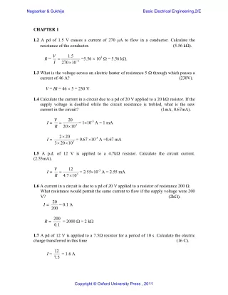
Nagsarkar & Sukhija Basic Electrical Engineering,2/E CHAPTER 1 1.2 A pd of 1.5 V causes a current of270 A to flow in a conductor. Calculate the resistance of the conductor. (5.56 k). 5 1 I 1.3 What is the voltage across an electric heater ofresistance 5 through which passes a current of 46 A? (230V). V = IR = 46 5 = 230 V 1.4 Calculate the current in a circuit due to a pd of 20 V applied to a 20 k resistor. If the supply voltage is doubled while the circuit resistance is trebled, what is the new current in the circuit? (1mA, 0.67mA). 20 R 20 2 1.5 A p.d. of 12 V is applied to a 4.7k resistor. Calculate the circuit current. (2.55mA). 12 R 1.6 A current in a circuit is due to a pd of 20 V applied to a resistor of resistance 200 . What resistance would permit the same current to flow ifthe supply voltage were 200 V? (2k). 20= 0.1 A V . =5.56 103 = 5.56 k. R = 6 270 10 V = 110-3 A = 1 mA I = 3 20 10 = 0.67 10-3 A =0.67 mA I = 3 3 20 10 V = 2.5510-3 A = 2.55 mA I = 3 7 . 4 10 I = 200 200 . = 2000 = 2 k R = 0 1 1.7 A pd of 12 V is applied to a 7.5 resistor for a period of 10 s. Calculate the electric charge transferred in this time (16 C). 12 = 1.6 A I = 5 . 7 Copyright © Oxford University Press , 2011
Nagsarkar & Sukhija Basic Electrical Engineering,2/E Q = 1.6 10 = 16 C 1.8 What is the charge transferred in a period of 8 s by current flowing at the rate of 3.5 A? (28 C) Q = It = 3.5 8 = 28 C 1.10 A d.c. motor connected to a 230 V supply is developing 20kW at a speed of 1000 rpm has an efficiency of 0.85, calculate (a)the current and (b)the cost of the energy absorbed if the load is maintained constant for 12 h. Assume the cost of electrical energy to be Rs.2.50 per kWh. (102.3A, Rs.705.90) 10 20 v Cost of energy = 230 102.3 10-3 2.50 = Rs. 705.90 1.11An electric motor runs at 600 rpm when driving a load requiring a torque of 400 Nm. If the motor input is 30 kW, calculate the efficiency of the motor and the heat lost by the motor per minute, assuming its temperature to remain constant. (83.8%, 292.8kJ) 400 600 2 60 12 . 25 input power Heat loss /min = (30 25.12) 60 = 292.8 kJ 1.12 (b) A conductor of length l and radius r has a resistance of R Ω. If the volume of the conductor is V show that VR l R Assume that the resistivity of the conductor is . r ) ( r l R 3 p I = = 102.3 A 230 . 0 85 NT 2 Power output = = 25120 W, or 25.12 kW 60 power output = . 0 838 = 83.8 % 30 V 2 i r . ( ) , and, (ii) 4 l and volume V = r2l. R (i) Resistance of the conductor 2 2 2 4 V r l r or, . 2 V r or, 4 2 R Copyright © Oxford University Press , 2011
Nagsarkar & Sukhija Basic Electrical Engineering,2/E 2 2 VR V V 2 l (ii) Next, V 2 2 4 r 2 R VR l or, 1.13 A voltage of 440 V is applied across a parallel plate liquid resistor. If the resistor absorbs 50 kW, calculate the distance between the plates. Assume a resistivity of 25 Ω- cm for the liquid and a current density of 0.30 A/cm2. 58.67 cm Solution 50000 2 440 Resistance of the electrode R . 3 87 50000 Current flowing through the resistor R 113 . 64 A 440 64 . 113 2 Area of each of the electrode plate a 378 . 79 cm 3 . 0 . 3 87 378 . 79 Distance between the electrode plates l 58 . 67 cm 25 1.14 A conductor has a resistance of Rl ohms at t10C, and consists of copper with a resistance-temperature coefficient a referred to 00C. Find an expression for the resistance R2of the conductor at temperature t20C. Expression is developed in the text 1.15 The resistance temperature coefficients of two conductors A and B, at a temperature of t0C is αA and αB respectively. The resistors are connected in series such that their resistances are in the ratio of (RA /RB) = a. Derive an expression for the resistance temperature coefficient α, and the temperature t for the circuit. (a) If a = 4, A = 0.003/C and B = 0.0003/C, determine the value of α and the temperature t. (b) What is the ratio , / 005 . 0 0004 . 0 A a 0C 0 0 / C, and . 0 0025 / ? C of the resistors when B 1 (a) 1666.70 C (b) 1.8 A B , 1 a A B Solution t B R R t R R 1 and 1 The resistance When the resistors are connected in series R R R B A A A B 0 0 t 1 t R 2 1 A B 0 0 t Thus, A B Copyright © Oxford University Press , 2011
Nagsarkar & Sukhija Basic Electrical Engineering,2/E R t 1 A A a Also, R t 1 B B Substitution for t and simplification results in B a (a) Substitution of the given data gives = 0.0039 and t = 1666.67 C. (b) From the given data 005 . 0 1 1 A A B B a A B A a A B 1 . 0 005 . 0 0004 a . 1 84 . 0 0025 1.16 The field coil of a motor has a resistance of 500 at 15°C. By how much will the resistance increase if the motor attains an average temperature of 45 °C when running? Take = 0.00428/°C referred to 0°C. (60.33 ) ( R 00428 0 1 500 R45 = 560.33 . Hence increase in resistance = 60.33 . 1.17 Explain what is meant by the temperature coefficient of resistanceof a material. A copper rod, 0.6m long and 4mm in diameter, has a resistance of 825 at 20°C. Calculate the resistivity of copper at that temperature. If the rod is drawn out into a wire having a uniform diameter of 0.8 mm, calculate the resistance of the wire when its temperature is 60°C. Assume the resistivity to be unchanged and the temperature coefficient of resistance of copper to be 0.00426/°C. (0.01727 -m, 0.0.6035 ) 10 4 4 . R ) 1 45 45 0 ( ) 1 15 15 0 R ( . ) 45 45 or, ( . ) 1 0 00428 15 2 6 3 825 10 = 0.01727 10-6-m 20 = 0 6 2 4 When diameter is 0.8 mm then the length = 0.6 = 15 m 8 . 0 15 R20 = 1.727 10-8 = 0.5156 ( 8 . 0 ( 3) 2 ) 4 / 10 1.18 A coil of insulated copper wire has a resistance of 160 at 20°C. When the coil is connected across a 240 V supply, the current after several hours is 1.35 A. Calculate R60 = R20 (1 + 0.00426 40) = 0.5156 1.1704 = 0.6035 Copyright © Oxford University Press , 2011
Nagsarkar & Sukhija Basic Electrical Engineering,2/E the average temperature throughout the coil, assuming the temperature coefficient of resistance of copper at 20°C to be 0.0039/°C. (48.5°C) Rt = 240/1.35 =177.78 20 = 0.0039 = 0/(1+0 20) 0 = 0.00423/°C. t 177 78 . 1 00423 . 0 ; t1 = 48.5°C. 160 1 00423 . 0 20 1.19 The voltage waveform shown in Fig.1.33 is applied across a parallel combination of a capacitor of 0.4F and a resistor of 4 Ω. Plot the wave forms of the currents through the capacitor, resistor and the total current and determine (a) energy dissipated in the resistor, (b) maximum energy stored in the capacitor, (c) energy supplied by the source, (d) total charge flow through the resistor, and (e) average resistor voltage. Fig. 1.33 (a) 66.67 J, (b) 80 J, (c) 66.67 J, (d) 5 C, (e) 13.33 V Solution Mathematically, the applied voltage is expressed as sec. 0 0 t v t Current through the resistor 4 and the total current t i t i i c R T . The plot of the currents is shown below in Fig. S1.19. Energy dissipated in the resistor is given by7 1 0 4 4 1 t v t t t 20 0 0 . 1 sec. v t t 20 40 0 . 1 0 . 2 sec. t d v , the current through the apacitor t , iR t iC t v 4 . 0 dt 2 2 1 2 1 2 100 100 t t 20 20 40 0 1 2 2 WR dt dt t dt t t dt 400 400 66 . 67 J 20 2 Maximum energy stored in the capacitor 4 . 0 80 J 2 Since a capacitor consume no energy, the energy supplied by the source is 66.67 J Charge flowing through the resistor is given by C 5 4 4 1 0 67 . 66 R Q 1 2 t t 20 20 40 QR dt dt W R Averagevol tage 13 33 . V 5 Copyright © Oxford University Press , 2011
Nagsarkar & Sukhija Basic Electrical Engineering,2/E Fig. S1.19 1.20 State how the physical parameters of a capacitor are related to its capacitance and discuss the significance of the permittivity of the dielectric. The distance between the plates of a capacitor is 6 mm and its dielectric material has a relative permittivity of 3. Copyright © Oxford University Press , 2011
Nagsarkar & Sukhija Basic Electrical Engineering,2/E Another sheet of dielectric material of relative permittivity εr and thickness 9 mm is inserted by moving the plates apart. If the capacitance of the composite capacitor is half that of the original capacitor, determine the value of εr. Solution Knowing that capacitance is directly proportional to the relative permittivity and inversely to the distance, it is seen that 3 1 C F where A K Similarly K C F The capacitance of the composite capacitor is written as C C C Thus, 9 3 or 1000 9 1000 6 1.21 State Coulomb’s law and there from define electric field. A voltage of 25 kV is applied to a parallel plate capacitor whose capacitance is 2.5×10─4 µF. If the area of each plate is 110 cm2 and are separated by a dielectric material of thickness 3 mm, calculate (a) the total charge in coulombs, (b) the per sq. m. charge density, (c) relative permeability of the dielectric, and (d) potential gradient. 6.25µC, (b) 568.18µC/m2 (c) 7.7 (d) 83.33 kV/cm 4.5 K 6 1000 0 r 2 9 1000 C C 1 2 1 C C or 1 2 2 1 2 rK K 3 C 5 . 4 r 1 6 Solution Data: Q F, V = 25000 V, A = 110 × 10-4 m2, d = 3 × 10⁻³ m C 25 . 6 25000 10 25 . 6 A 10 5 . 2 A 25000 d 1.22 A parallel plate condenser has an area of A cm2 and the distance between the plates 10 C 5 . 2 V 10 5 . 2 10 C (a) Q 2 568 . 18 C/m 4 110 10 (b) Charge density 10 3 C d 3 10 (c) Relative permittivity . 7 70 r 12 . 8 4 110 10 84 10 0 V (d) Potential gradient kV/cm 33 . 83 3 . 0 r determine how the is d mm. If the relative permittivity of the dielectric material is energy stored in the capacitor will vary, with each factor, when a voltage of V volts is applied across it? 2 AV WC d Solution Copyright © Oxford University Press , 2011
Nagsarkar & Sukhija Basic Electrical Engineering,2/E 4 A A 10 C r r 0 0 1 3 d 10 d 10 F 2 AV 10 W C r 0 d 2 J Energy stored 2 AV WC d Or 1.24 A current-carrying conductor is situated at right angles to a uniform magnetic field having a density of 0.4 T. (a) Calculate the force (in newtons per metre length) on the conductor when the current is 100 A. (b)Calculate the current in the conductor when the force per metre length of the conductor is 25 N. (40 N, 62.5 A) Force F = BIl = 0.4 100 1 =40 N Force = 25 N; I = 25/(0.41)= 62.5 A 1.27 The coil of a moving-coil loudspeaker has a mean diameter of 40 mm and is wound with 1000 turns. It is situated in a radial magnetic field of 0.4 T. Calculate the force on the coil, in newtons, when the current is 10 mA. (0.5024N) F= 0.4 0.01 0.04 1000 = 0.5024 N 1.28 A square coil of side l cm and T number of turns revolves about its axis at right angles inside a magnetic field of density B Wb/m2. If the speed of the coil is N rpm, derive an expression for the instantaneous value of the induced emf. If l = 15 cm, B = 0.5 Wb/m2 and N = 1200 rpm, determine (a) maximum, and (b) minimum value of the induced emf. (c) What are the respective angles made by the plane of the coil with the magnetic field? (d) Calculate the angle made by the plane of the coil with the magnetic field when the instantaneous value of the induced emf is 185 V. (a) 212.06 V, 900, (b) 0 V, 00, (c) 60.740 Solution From Eq. 4.1, the instantaneous value of the induced emf per turn in the coil is given by sin 2Blu e The speed of rotation of the coil is given by N l u The instantaneous value of the induced emf in T turns of the coil is written as sin 2 N TBl e V For the given data, 60 0 e V and it occurs at 0 degrees 185 sin 60 2 60 2 5 . 0 2 150 . 0 15 1200 e 212 06 . max 2 (a) V and it occurs at degrees min (b) 1 0 0 V and it occurs at degrees (c) 60 . 74 212 . 06 Copyright © Oxford University Press , 2011
Nagsarkar & Sukhija Basic Electrical Engineering,2/E 1.29 A conductor, 750 mm long, is moved at a uniform speed at right angles to its length and to a uniform magnetic field having a density of 0.4 T. If generated e.m.f. in the conductor is 3 V and the conductor forms part of a closed circuit having a resistance of 0.5, calculate: (a) the velocity of the conductor in metres per second; (b) the force acting on the conductor in newtons; (c) the work done in joules when the conductor has moved 500 mm. (10 m/s, 1.8 N, 0.9 J) l = 0.75 m; B = 0.4 T; e = 3 V; R = 0.5 . (a) e = Blu; or, 3 = 0.4 0.75 u; 3 3= 6 A u = = 10 m/s 4 . 0 . 0 75 (b) I = 5 . 0 F = BlI = 0.4 0.75 6 = 1.8 N 1.30 In a coil of 120 turns, the flux is varying, with time as shown in Fig. 1.38. If 025 . 0 m Wb and T = 0.04 sec., determine the value of the statically induced emf. Plot to scale the waveform of the induced voltage. Fig. 1.38 (c) w = F distance = 1.8 0.5 = 0.9 J 300V Solution t T 0 2 sec., the variation of flux ϕ with time is expressed as For the period 4t T 1 m Wb T t T 2 sec., the variation of flux ϕ with time is expressed as Similarly, for the period 4t T 3 m From Eq. (1.45) and the application of Lenz’s law the statically induced emf in the coil, for the two periods is calculated as under 2 0 T t sec., dt 2 0 T t sec., d dt From the given data, the magnitude of the statically induced voltage is written as 025 . 0 480 e V The waveform of the induced voltage is plotted in Fig. S1.30 .below. Wb 480 d d 4 120 m For the period V e t 120 1 m dt T T Similarly, for the period d e 120 480 4 m V t 120 1 m dt T T 300 . 0 04 Copyright © Oxford University Press , 2011
Nagsarkar & Sukhija Basic Electrical Engineering,2/E Fig S1.30 1.31 The axle of a certain motorcar is 1.6 m long. Calculate the generated e.m.f. in it when the car is travelling at 120 km/h. Assume the vertical component of the earth's magnetic field to be 40 T. (2.13mV) l = 1.6 m; B = 0.4 10-6 T; u = 120 km/hour = 100/3 m/s; e = 1.6 0.4 10-6100/3 = 2.13 mV 1.32 A coil of 2500 turns gives rise to a magnetic flux of 5 mWb when carrying a certain current. If this current is reversed in 0.2 s, what is the average value of the e.m.f. induced in the coil? (125 V) N = 2500; = 5 10-3 Wb; t = 0.2 s 10 5 2 = 125 V 3 e = 2500 2 . 0 1.33A short coil of 500 turns surrounds the middle of a bar magnet. If the magnet sets up a flux of 60 Wb, calculate the average value of the e.m.f. induced in the coil when the latter is removed completely from the influence of the magnet in 0.04 s. (0.75 V) N = 500; = 60 10-6 Wb; t = 0.04 s 10 60 = 0.75 V 6 e = 500 . 0 04 1.35 For the circuit shown in Fig. 1.36 determine the value of source current IS for the following operating conditions: (a)the source voltage VS = 12 V, and IAB = 0; (b)the source voltage VS = 15 V, and IAB = 3 A. [(a) 4 A; (b) 1 A] Fig. 1.36 Copyright © Oxford University Press , 2011
Nagsarkar & Sukhija Basic Electrical Engineering,2/E (a) VS = 12 V; IAB = 0; 2 VAO = 12 = 8 V; VBO = 8 V, as IAB = 0. 2 1 IS = 8/2 = 4 A (b) VAB = IAB 2 = 3 2 = 6 V VBO = VAOVAB = 8 6 = 2 V IS = (2/2) = 1 A 1.36 In the circuit of Fig. 1.37, v(t) = 3 –t. Use Kirchhoff’s laws and the volt-ampere relations for the elements to determine the source current iS(t). (4.8–t) Fig. 1.37 t e 12 4 1 iAB = iR + iB = 6e-t di 6 4 . 0 e dv d 3 t t t iR = ; iB = C e e 2 3 ( ) 6 dt dt t t AB vAB = L e e 4 . 2 dt vA = vB + vAB = 3e-t 2.4 e-t = 0.6 e-t d = 1.2 e-t iA = 2 t e 6 . 0 ( ) dt iS(t) = iB + iAB = 6e-t1.2 e-t = 4.8 e-t 1.37 Repeat Problem 1.21 for v(t) = 4 sin t. (3.2 sin t + 9.6 cos t) t sin 16 4 1 dt dt iAB = iR + iB = 16 sin t + 8 cos t diAB 4 . 6 ) sin 8 cos 16 ( 4 . 0 dv d 4 sin ; iB = t iR = = C t t 2 4 ( sin ) 8 cos 2 . 3 vAB = L t t t t cos sin dt vA = vB + vAB = 4 sin t + 6.4 cos t 3.2 sin t = 0.8 sin t + 6.4 cos t Copyright © Oxford University Press , 2011
Nagsarkar & Sukhija Basic Electrical Engineering,2/E dvA= 2(0.8 cos t 6.4 sin t) = 1.6 cos t 12.8 sin t iA = 2 dt iS(t) = iB + iAB = 9.6 cos t + 3.2 sin t 1.38 In the circuit of Fig. 1.38, i(t) = –15e–2t. Use Kirchhoff’s laws and the volt-ampere relations for the elements to determine the source voltage vS(t). (22e–t) Fig. 1.38 vA =i(t) 1/5 = –15e–2t 1/5 = –3 e–2t dv C = 5 ( dt iL = iA + i(t) = 30 e-2t –15e–2t = 15e–2t vR = 2 15e–2t = 30e–2t di L 30 6 vR = 2 15e–2t = 30 e–2t vS(t) = vA + vL + vR= 22 e–2t 1.39 Repeat Problem 1.22 for i(t) = 20 sin t. (40.67 sin t + 43.33 cos t) vA =i(t) 1/5 = 20 sin t 1/5 = 4 sin t d = 20 cos t d = 30 e-2t 2t iA = e 3 ) dt 1 t t 2 2 L vL = e e 5 dt iA = 5 t 4 ( sin ) dt iL = iA + i(t) = 20 (sin t + cos t) vR = 2 20 (sin t + cos t) = 40 (sin t + cos t) 1 dt di L vL = L t t 20 (cos sin ) 6 1 t t + 40 (sin t + cos t) vS(t) = vA + vL + vR= 4 sin t + 20 (cos sin ) 6 = 40.67 sin t + 43.33 cos t Copyright © Oxford University Press , 2011