Download
1 / 14

E N D
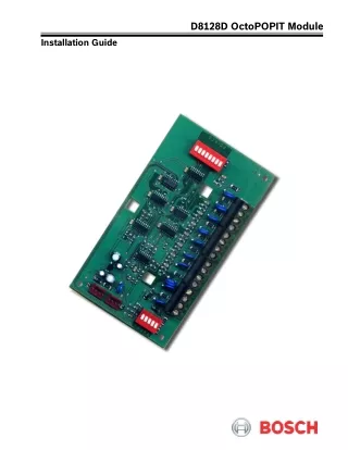
D8128D OctoPOPIT Module Installation Guide
D8128D Contents Table of Contents 1.0 Introduction........................................................................................................................................................................................................3 1.1 Document Organization....................................................................................................................................................3 1.2 Tips, Important Notes, Cautions, and Warnings.......................................................................................................3 1.3 Listings...................................................................................................................................................................................3 1.3.1 Requirements for Fire Initiation Applications.............................................................................................................3 2.0 Overview 2.1 Specifications.......................................................................................................................................................................3 2.2 Module Description ............................................................................................................................................................4 3.0 Installation 3.1 Setting OctoPOPIT Switches..........................................................................................................................................6 3.1.1 Address Switches...............................................................................................................................................................6 3.1.2 Point DIP Switches.............................................................................................................................................................6 3.2 Mounting the D8128D .......................................................................................................................................................6 3.3 Wiring......................................................................................................................................................................................8 3.3.1 Connecting the D8128D to the Control Panel using the Terminal Strip............................................................8 3.3.2 Wiring the D8128D to the Control Panel using Molex Connectors..................................................................10 3.4 Wiring OctoPOPIT Sensor Loops...............................................................................................................................10 3.4.1 OctoPOPIT Sensor Loops............................................................................................................................................10 3.4.2 Switch Settings for D9412, D9412G, D9124, and D9112...................................................................................11 3.4.3 Switch Settings for D7412, D7412G, D7212, and D7212G...............................................................................12 3.4.4 Switch Settings for D9112B1.......................................................................................................................................12 3.4.5 Switch Settings for D7212B1.......................................................................................................................................13 Figures Figure 1: D8128D OctoPOPIT Layout Figure 2: Mounting Enclosure Figure 3: Wiring the D8128D to the Control Panel Using a D8125 POPEX ..................................................................9 Figure 4: Wiring Multiple D8128D Modules Using Molex Connectors..........................................................................10 Figure 5: D8128D Sensor Loops...............................................................................................................................................10 Tables Table 1: Document Organization.................................................................................................................................................3 Table 2: D8128D Specifications...................................................................................................................................................4 Table 3: Compatible Control Panels...........................................................................................................................................4 Table 4: Maximum D8128D Connections..................................................................................................................................5 Table 5: Number of D8128D Modules Used with the D8129 Modules............................................................................5 Table 6: Terminal Strip Connections...........................................................................................................................................8 Table 7: D8128D Switch Settings (D9412, D9412G, D9124, and D9112)..................................................................11 Table 8: D8128D Switch Settings (D7412, D7412G, D7212, and D7212G)..............................................................12 Table 9: D8128D Switch Settings (D9112B1).......................................................................................................................12 Table 10: D8128D Switch Settings (D7212B1)....................................................................................................................13 5 7 F01U070537-06 D8128D Installation Guide Page 2 © 2008 Bosch Security Systems, Inc.
D8128D 1.0 The D8128D OctoPOPIT Module combines the functions of the D8125 POPEX Module and the D8127/D9127 POPIT Modules to provide eight off-board points (Class B [Style B]) in a single module. You can wire both the D8128D OctoPOPIT and D8125 POPEX in parallel to the Zonex Bus Terminals on the same control panel. For a list of compatible control panels and accessories, refer to Section 2.0 Overview on page 3. Also refer to the D9412GV2/D7412GV2 Approved Applications Compliance Guide (P/N: F01U003639). 1.1 Document Organization Table 1 identifies the sections of this document. Introduction Section 1 2 3 Description Introduction Overview Installation Table 1: Document Organization 1.2 Throughout this document, helpful tips, important notes, cautions and warnings are presented for the reader to keep in mind. These appear different from the rest of the text as follows: Tips, Important Notes, Cautions, and Warnings Heed for successful operation and programming. Can also include tips and shortcuts. Caution the operator that physical damage to the program and/or equipment can occur. Warn of the possibility of physical damage to the operator, program, and/or equipment. 1.3 The D8128D is Underwriters Laboratories, Inc. (UL) Listed for Local or Police Connected Burglary Alarm, Central Station Burglary Alarm, Household Burglary Alarm applications, and Commercial Fire applications (UL864 and NFPA 72). The D8128D is also suitable for Fire Supervisory applications, such as indicating circuit supervision using the D192C Bell Circuit Supervision Module, sprinkler supervision, and valve tamper protection. Listings 1.3.1 You can connect non-powered, fire initiating devices such as pull-stations, heat detectors, and UL Listed four- wire smoke detectors directly to the D8128D point inputs. The D125B Dual Powered Loop Interface Module or the D129 Dual Class A Module zone outputs can be connected directly to the D8128D point inputs. Use the D125B to connect two-wire smoke detectors. Generally, the D129 is used for connecting waterflow switches. The D125B or D129 and the OctoPOPIT can be mounted in the same enclosure with the control panel or in a separate enclosure connected to the control panel’s enclosure by conduit no more than 20 ft (6 m) long. Requirements for Fire Initiation Applications The D7212G Control Panel is not listed for commercial fire applications. 2.0 2.1 Overview Specifications © 2008 Bosch Security Systems, Inc. D8128D Installation Guide Page 3 F01U070537-06
D8128D Compatible Panels Power Requirements Refer to Table 3. Voltage: 12 VDC nominal Current: Standby (supervised): 25 mA maximum Alarm (all points shorted): 50 mA maximum Environmental Considerations Operating Temperature: +32°F to +120°F (0°C to +49°C) Relative Humidity: 0% to 93% Loop End-of-Line (EOL) Resistance: 1 kΩ Wiring Resistance: 100 Ω maximum Response Time: Approximately 1 sec. OctoPOPIT sensor loops are supervised with a 1 kΩ EOL resistor, D105BL or D105FL, for fire supervisory applications. Cabling Burglary Applications: D8128D OctoPOPITs can be installed up to 200 ft (61 m) 4 Ω maximum from the control panel using standard 4-conductor 22 AWG (0.8 mm) wire. Use shielded cable when the D8128D is located outside the control panel enclosure. Use UL Listed fire rated cable approved by the AHJ when connecting fire- initiating or fire-supervisory devices to the D8128D. You can locate the D8128D OctoPOPITs up to 200 ft (61 m), 4 Ω maximum from the control panel. You must mount the D8128D in a D8109 or D8108A Enclosure. When a D125B or D129 is required, mount it in the same enclosure as the D8128D OctoPOPIT. Control Panel Wiring Connection Requirements (Maximum Wire Fire Applications: Resistance: 4 Ω Ω) Maximum Distance 200 ft 200 ft 60 m 60 m Wire Size 22 AWG 18 AWG 0.6 mm 1.0 mm Table 2: D8128D Specifications 2.2 The D8128D combines the functions of the D8125 POPEX and the D8127/D9127 POPIT to provide eight off- board points in a single module. You can wire both the D8128D OctoPOPIT and D8125 POPEX in parallel to the Zonex Bus Terminals on the same control panel. Review the power outputssection of your control panel’s operation and installation guide to ensure you provide enough power for the OctoPOPITs and other powered devices you want to connect to your system. Use the D8128D with the control panels shown in Table 3 on page 4. For additional D8128D installation information, refer to the D9412GV2/D7412GV2 Approved Applications Compliance Guide (P/N: F01U003639). Module Description Bosch Security Systems Control Panel D7212GV2/ D7212G/ D7212 D7412GV2/ D7412G/ D7412 D9412GV2/ D9412G/D941 2 D9124GV2/ D9124 OctoPOPIT D7212B1 D9112B1 D9112 ? ? ? ? ? ? ? D8128D Table 3: Compatible Control Panels The maximum number of D8128D Modules that can be connected to your system depends on the control panel being used (Table 4).Refer to Table 7 through Table 10 on pages 11 to 13 for proper switch settings. F01U070537-06 D8128D Installation Guide Page 4 © 2008 Bosch Security Systems, Inc.
D8128D Control Panel Maximum Number of D8128D Modules D9412GV2/D9412G 30 D9412 30 D9112 30 D9112B1 16 D9124 w/D9112LTB 16 D9124 w/D9112LTB-EX 30 D9124 w/D9412GLTB 30 D7412GV2/D7412G 9* D7412 9* D7212 9* D7212B1 5 D7212GV2/D7212G 4 * Use three points on the last OctoPOPIT. Table 4: Maximum D8128D Connections The number of D8128D OctoPOPITs connected limits the number of D8129 OctoRelays that can be connected to each Zonex Terminal on the D9412G Control Panels. Using the D8129 OctoRelays and D8128D OctoPOPITs together on the same Zonex Terminals is limited and depends on the number of D8128D OctoPOPITs and D8129 OctoRelays connected to a single Zonex Bus. Table 5 shows the maximum number of D8128Ds and D8129s you can connect to a single Zonex Bus. Number of D8128D Modules Connected to a Single Zonex Bus 9 10 11 12 13 14 Maximum Number of D8129 Modules to Connect 6 5 4 3 1 1 Table 5: Number of D8128D Modules Used with the D8129 Modules 3.0 Before installing the D8128D OctoPOPIT, become familiar with the operation and installation guide and the program entry guide corresponding to your system. Follow the four-step process for the most effective installation: • • • • Wire the OctoPOPIT sensor loops. Installation Set the OctoPOPIT switches. Mount the OctoPOPIT to the enclosure. Wire the OctoPOPIT. © 2008 Bosch Security Systems, Inc. D8128D Installation Guide Page 5 F01U070537-06
D8128D 3.1 The D8128D has two sets of DIP switches. Use the DIP switches on the top of the unit (with the terminal strip along the left edge) to set the OctoPOPIT address. Use the DIP switches at the bottom of the unit to enable or disable individual points connected to the OctoPOPIT. Setting OctoPOPIT Switches Molex Connectors Address DIP Switches 3.1.1 The switches on the D8128D OctoPOPIT set point assignments and line termination (Figure 1). These switches are easier to set before mounting the D8128D in the enclosure. Address Switches Terminal Strip 3.1.1.1 Address Assignment Switches Switches 1, 2, 3, and 4 assign the OctoPOPIT sensor loops to point numbers on the control panel. Table 7 through Table 10 on pages 11 and 13 show the OctoPOPIT switch settings for point assignments, depending on the control panel being used. Point DIP Switches 1 2 3 4 5 Points 6 7 8 Figure 1: D8128D OctoPOPIT Layout 3.1.1.2 Line Termination Switch Settings Switch 5 sets line termination. • If no D8125 POPEX is connected to ZONEX 1, set switch 5 of only one D8128D connected to those terminals to the ON position. If a D8125 POPEX is connected to ZONEX 1, set switch 5 of all D8128Ds connected to those terminals to the OFF position. If no D8125 POPEX is connected to ZONEX 2, set switch 5 of only one D8128D connected to those terminals to the ON position. If a D8125 POPEX is connected to ZONEX 2, set switch 5 of all D8128Ds connected to those terminals to the OFF position. • • • 3.1.2 Each point connected to the D8128D is enabled or disabled by turning its respective DIP switch to the closed or open position, respectively. For example, to disable a device connected to Terminal P3 (Point 3), move DIP Switch 3 to the OPEN position. Use the point DIP switches to disable conflicting points, such as when a D9210B Access Control Module must be assigned to a point within the range of the D8128D OctoPOPIT. In this example, a D9210B is assigned to Point 20. On the same system, a D8128D OctoPOPIT is assigned to Points 17 through 24. Moving the DIP switch for Point 4 to the OFF position effectively disables Point 20, allowing normal operation of the D9210B and the OctoPOPIT. Terminate each OctoPOPIT sensor loop with a 1 kΩEOL resistor. Attach a resistor even if you do not enable the loop. Point DIP Switches 3.2 You can install the D8128D in the enclosure with the control panel using standard four-conductor 22 AWG (0.8 mm) wire or in a separate enclosure (such as D8103, D8108A, or D8109) up to 200 ft (61 m) from the control panel. Use the recommended shielded standard four-conductor 22 AWG (0.8 mm) wire. Refer to the cabling specifications in Table 2 on page 3when using the D125B or the D129. For UL Listed systems, mount the D8128D in a tamper-proof enclosure. Mounting the D8128D F01U070537-06 D8128D Installation Guide Page 6 © 2008 Bosch Security Systems, Inc.
D8128D To install the D8128D in the control panel enclosure: 1.Align the D8128D with any of the four mounting locations in the enclosure (Figure 2). 2.Secure the module to the enclosure using the supplied screws. Use the D137 Mounting Bracket to install D8128D Modules in enclosures with no module-mounting locations available. Point Chart Label Module Mounting Locations Tamper Switch Mounting Location Mounting Skirt Hooks Module Mounting Locations Mounting Skirt Hole Figure 2: Mounting Enclosure © 2008 Bosch Security Systems, Inc. D8128D Installation Guide Page 7 F01U070537-06
D8128D 3.3 Wiring Disconnect all power to the control panel before beginning any work with the internal components. Serious injury could result from electrical shock. To power down the control panel, disconnect the positive (red) battery lead at the battery and unplug the transformer. The D8128D can be installed up to 200 ft (61 m) from the control panel. Use one of the two following methods to connect the D8128D to a control panel: • • Connect the D8128D to the control panel using Molex connectors (P1 and P2). Wire the D8128D to the control panel using the terminal strip located on the side of the module. AC Induction: Avoid installing zonex data wires and zonex input (sensor loop) wires around any AC conduit/wiring or electrical devices that emit fields of electromagnetic interference (EMI). 3.3.1 When connecting the D8128D to the control panel using the D8128D terminal strip, make the following connections. D8128D D9412G/D9412/D9112/D9112B1/D91 24 Commo n Out Zonex 1 = Terminal 27 Zonex 2 = Terminal 25 In Zonex 1 = Terminal 28 Zonex 2= Terminal 26 +12 V Terminal 24 Connecting the D8128D to the Control Panel using the Terminal Strip D8128D D7412G/D7412/D7212G/D7212B1/D7212 Terminal 23 Commo n Out In +12 V Terminal 9 Terminal 27 Terminal 28 Terminal 3 Table 6: Terminal Strip Connections Figure 3 on page 9 shows how to wire the D8128D to the control panel using a D8125 POPEX. F01U070537-06 D8128D Installation Guide Page 8 © 2008 Bosch Security Systems, Inc.
D8128D ZONEX BUS 1 Switch 1 CLOSED (Ponts 9 through 72) ZONEX BUS 1 Switch 1 OPEN (Ponts 73 through 127) Supervised Bus 1 Bus 1 cont’d Sensor Loops Sensor Loops 28 27 26 25 24 1 2 3 4 5 6 7 8 1 2 3 4 5 P O I N T S 6 7 8 P O I N T S 23 ZONEX BUS 2 Switch 1 CLOSED (Ponts 129 through 192) ZONEX BUS 2 Switch 1 OPEN (Ponts 193 through 247) Terminal 9 on the D7212/D7212G/D7412 Supervised Terminal 3 on the D7212/D7212G/D7412 Bus 2 Bus 2 cont’d Sensor Loops Sensor Loops 1 2 3 4 5 6 7 8 1 2 3 4 5 6 7 8 P O I N T S P O I N T S P O I N T S P O I N T S Note: Do not loop wires around the terminals. D8125 POPEX All wiring is power limited. (-) (-) (+) (+) D9127U DAT LOO - Supervised - - + + + 33 kΩ EOL (P/N: F01U009012B) GND OUT Positive (+) Negative (-) IN Zone Expansion Loop AUX Figure 3: Wiring the D8128D to the Control Panel Using a D8125 POPEX © 2008 Bosch Security Systems, Inc. D8128D Installation Guide Page 9 F01U070537-06
D8128D 3.3.2 Each D8128D includes a 12-in. (30 cm) female-to-female Molex cable assembly. P1 and P2 are Molex connectors that parallel the COM, IN, OUT and +12 VDC terminals on the terminal strip. In installations using multiple D8128D Modules, use these connectors (as opposed to terminals) with the supplied cable. When connecting D8128D Modules directly to the control panel, the terminal strip might be easier to use. The supplied Molex connectors are keyed. A Molex plug can only fit in one direction. Ensure the connector is correctly attached, the red wire is on the bottom of P1 (or P2), and the black wire is on the top. When connecting multiple D8128D Modules to a control panel, you can connect the control panel terminals to P1 or the Com, In, Out, and +12 V Terminals on the first D8128D. Then connect P2 of the first D8128D to P1 of the second D8128D and so on. Refer to Figure 4. Wiring the D8128D to the Control Panel using Molex Connectors P2 P2 P2 Up to 15 per ZONEX Bus P1 P1 P1 COM IN OUT+12V COM IN OUT+12V COM IN OUT+12V Second D8128D Third D8128D First D8128D Control Panel 28 27 26 25 TERMINAL 3 ON D9412/D9112/D7212/ D7212G/D7412 TERMINAL 9 ON D9412/D9112/D7212/ D7212G/D7412 24 23 Figure 4: Wiring Multiple D8128D Modules Using Molex Connectors 3.4 3.4.1 Only the resistance on the loop limits the number of normally open (NO) and/or normally closed (NC) detection devices each sensor loop can supervise. Resistance on each sensor loop must be less than 100 ? with the detection devices connected. Certain UL and NFPA applications can limit the number of detection devices. Refer to the appropriate UL or NFPA standards. The OctoPOPIT detects open, short, normal, and grounded circuit conditions on its sensor loops and transmits the conditions to the control panel. Each sensor loop is assigned a point number and transmits to the control panel separately. Use twisted-pair wire for the OctoPOPIT sensor loops to avoid EMI problems. Run wires away from the premises telephone and AC wiring. If you suspect a noisy environment, use shielded cable. Wiring OctoPOPIT Sensor Loops OctoPOPIT Sensor Loops D8128D OctoPOPIT COM IN OUT+12V P1 COM P2 P3 COM P4 P5 COM P6 P7 COM P8 First D8128D TO ADDITIONAL OCTOPOPIT SENSOR LOOPS Control Panel 28 27 OCTOPOPIT SENSOR LOOPS 26 25 TERMINAL 3 ON D9412/D9112/D7212/ D7212G/D7412 TERMINAL 9 ON D9412/D9112/D7212/ D7212G/D7412 24 23 1 kΩ EOL RESISTOR (P105BL, 15-03130-004) Figure 5: D8128D Sensor Loops F01U070537-06 D8128D Installation Guide Page 10 © 2008 Bosch Security Systems, Inc.
D8128D The OctoPOPIT has two rows of terminal numbers. In the row closest to the terminal blocks, the positive outputs for the sensor loops are labeled P1 to P8. Sensor loop outputs P1 and P2, P3 and P4, P5 and P6, and P7 and P8 share common terminals. The common terminals for each pair are labeled COM. Terminate each OctoPOPIT sensor loop with a 1 k??EOL resistor. Attach a resistor even if you do not enable the loop. The OctoPOPIT includes a D105BL resistor for each sensor loop. Do not to duplicate point assignments. Points do not function properly if assigned to both an OctoPOPIT sensor loop and a POPIT, to two OctoPOPIT sensor loops, or to two POPITs. 3.4.2 Switch Settings for D9412, D9412G, D9124, and D9112 ZONEX 1 Points 9 through 127 9 to 16 17 to 24 25 to 32 33 to 40 41 to 48 49 to 56 57 to 64 65 to 72 73 to 80 81 to 88 89 to 96 97 to 104 105 to 112 113 to 120 121 to 127 Table 7: D8128D Switch Settings (D9412, D9412G, D9124, and D8128D Address Switches ZONEX 2 Points 129 through 247 Refer to Table 7 to set the OctoPOPIT switches for use with the D9412, D9412G, D9124, and D9112 Control Panels. Points 128 and 248 are reserved for ZONEX Bus supervision. Note:For the OctoPOPITs assigned to Points 121 through 127 and 241 through 247, set Point Input Switch 8 to the OFF position. * Line Termination Switch. Refer to Section 3.1.1.2 Line Termination Switch Settings on page 6. 1 2 3 4 5 ON ON ON ON ON ON ON ON OFF OFF OFF OFF OFF OFF OFF ON ON ON ON OFF OFF OFF OFF ON ON ON ON OFF OFF OFF ON ON OFF OFF ON ON OFF OFF ON ON OFF OFF ON ON OFF ON OFF ON OFF ON OFF ON OFF ON OFF ON OFF ON OFF ON * * * * * * * * * * * * * * * 129 to 136 137 to 144 145 to 152 153 to 160 161 to 168 169 to 176 177 to 184 185 to 182 193 to 200 201 to 208 209 to 216 217 to 224 225 to 232 233 to 240 241 to 247 D9112) © 2008 Bosch Security Systems, Inc. D8128D Installation Guide Page 11 F01U070537-06
D8128D 3.4.3 Switch Settings for D7412, D7412G, D7212, and D7212G ZONEX 1 Points 9 through 75 the D7412, D7412G, D7212, and D7212G Control Panels. * Line Termination Switch. Refer to Section 3.1.1.2 Line Termination Switch Settings). Note: For the OctoPOPITs assigned to Points 73 to 75, set Point Input Switches 4 through 8 to the OFF position. Note: The D7212G supports Points 9 to 40 only. D8128D Address Switches Refer to Table 8 to set the OctoPOPIT switches to use with 1 2 3 4 5 9 to 16 17 to 24 25 to 32 33 to 40 41 to 48 49 to 56 57 to 64 65 to 72 73 to 75 ON ON ON ON ON ON ON ON OFF ON ON ON ON OFF OFF OFF OFF ON ON ON OFF OFF ON ON OFF OFF ON ON OFF ON OFF ON OFF ON OFF ON * * * * * * * * * Table 8: D8128D Switch Settings (D7412, D7412G, D7212, and D7212G) 3.4.4 Switch Settings for D9112B1 ZONEX 1 Points 9 through 71 9 to 16 17 to 24 25 to 32 33 to 40 41 to 48 49 to 56 57 to 64 65 to 71 D8128D Address Switches Refer to Error! Reference source not found. to set the OctoPOPIT switches to use with the D9112B1 Control Panel. Points 72 and 136 are reserved for Zonex Bus supervision. * Line Termination Switch. Refer to Section 3.1.1.2 Line Termination Switch Settings on page 6. Note: For the OctoPOPITs assigned to Points 65 to 71 or 129 to 135, set Point Input Switch 8 to the OFF position. ZONEX 2 Points 73 through 135 73 to 80 81 to 88 89 to 96 97 to 104 105 to 112 113 to 120 121 to 128 129 to 135 1 2 3 4 5 ON ON ON ON ON ON ON ON ON ON ON ON OFF OFF OFF OFF ON ON OFF OFF ON ON OFF OFF ON OFF ON OFF ON OFF ON OFF * * * * * * * * Table 9: D8128D Switch Settings (D9112B1) F01U070537-06 D8128D Installation Guide Page 12 © 2008 Bosch Security Systems, Inc.
D8128D 3.4.5 Switch Settings for D7212B1 ZONEX 1 Points 9 through 48 9 to 16 17 to 24 25 to 32 33 to 40 41 to 48 D8128D Address Switches Refer to OctoPOPIT switches for use with the D7212B1 Control Panel. * Line Termination Switch. Refer to Section 3.1.1.2 Line Termination Switch Settings Table 10 to set the 1 2 3 4 5 ON ON ON ON ON ON ON ON ON OFF ON ON OFF OFF ON ON OFF ON OFF ON * * * * * . Table 10: D8128D Switch Settings (D7212B1) After any programming or hardware change, do a functional test of the system as required by local codes. © 2008 Bosch Security Systems, Inc. D8128D Installation Guide Page 13 F01U070537-06
D8128D © 2008 Bosch Security Systems, Inc. 130 Perinton Parkway, Fairport, NY 14450-9199 USA (800) 289-0096 F01U070537-06 Installation Guide 10/08 D8128D Page 14 of 14