Download

1 / 37
370 likes | 406 Views
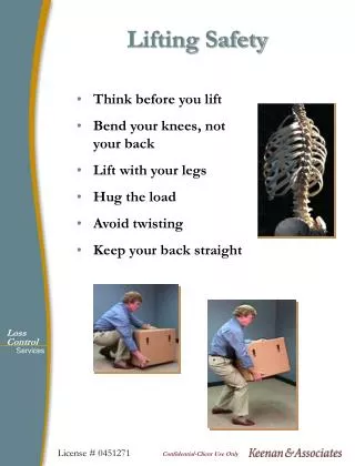
Lifting of flash butt welding machine for underground metro track pr

E N D
DINESH PAL 23 February 2021
As a courtesy to others please TURN OFFyour Mobile Phone Location of: - • Fire Escapes • Toilets • Smoking
What is a lifting operation?An operation concerned with the lifting or lowering of a load'. A 'load' is the item or items being lifted, which includes a person or people.
Types of Cranes :- • Mobile • Hydraulic • Overhead • Gantry • Tower
SAFETY DURING LIFTING OF FBW INTRODUCTION :- • The ballast less track is constructed as top down method where in :- • 60kg rails of 18m long are to be lowered first into the Tunnel. • Flash butt welding machine (32 MT approx..) will also to be lowered into the Station / Shaft/ Ventilation location of tunnel for welding of rails. • Rail pulling equipment’s (like rail shoe, rollers, and rail tongs) and small machineries like Bobcat or Tractor will also to be lowered into the tunnel wherever required to ease out the strain of rail pulling in tunnel for long length. • Gauge supporting frames, push pull lateral bracing, angle brackets, fasteners and shutters. Reinforcements and other consumables are also to be lowered in to the tunnel for track construction.
SAFETY DURING LIFTING OF FBW PREPARATION OF THE AREAS FOR EQUIPMENT HANDLING :- • The whole operation area shall be barricade. • The area shall be barricade with barrier tape & the “Lifting/Lowering in Progress” sign board will be displayed at site. • Unauthorised personnel will not be permit to enter the operational area. • Sufficient lighting arrangement shall be provided for the clear vision of the signal man to the crane operator and other activity locations both in tunnel and ground level. • Safe handling of FBW machine with hook arrangements as per load balance, proper clamping for the safety of the signal man. • Sufficient number of clamps with posts will be provide for the lighting requirements. • Need to check the shaft opening dimension before lowering of FBW machine in Tunnel. • To ensure the base slab area should be free from any obstructions while lowering.
SAFETY DURING LIFTING OF FBW LIFTING/LOWERING PROCEDURE • Assessment of the lift shall be undertaken and the lift method will be determined and planned by the Lifting/Lowering supervisor. • Crane Operators shall be trained and deemed competent for that Equipment. • Rigging of the load is carried out by competent rigging persons. • All Lifting/Lowering equipment and accessories shall be inspected visually before each use by the craneoperator and P&M in-charge.
SAFETY DURING LIFTING OF FBW The load shall not exceed the dynamic or static capacity of the Lifting/Lowering equipment. • Lifting plan to be prepared by assessing the load and the depth of tunnel at work site and the same to be incorporated in the plan.
Welding method • The rails shall be pushed to the welding head with specially designed tool & butt with each other. The welding head shall be placed on the joint and welding done.• On completion of the joint, the welded rail panel shall be pulled (manually) ahead and another rail placed at the end of panel, butt with it and welding done. Like this all the rails in a panel will be welded by concurrently pulling the rail panel ahead.
SAFETY REQUIREMENTS The Lifting/Lowering supervisorshouldensurethebarricadingand equipment’s working condition before applying for Lifting/Lowering permit. LIFTING/LOWER-ING ENGINEER • After ensuring the safety and working conditions of the crane, request for Lifting/Lowering permit duly filling necessaryinformation. • Attach the necessary documents to support the lift permit through P&M in- charge. P&M INCHARGE • Co-ordinate with the site engineer on the time slot confirmed for the Lifting/Loweringjob. • Validates the certificates produced by the Lifting/Loweringsupervisor. OHSE ENGINEER Acknowledge the Lifting/Lowering operation and copy the Lifting/Lowering Permit to Lifting/LoweringSupervisor. FLOW CHART FOR LIFTING/LOWERINGOPERATIONS
CONSTRUCTION ENGINEER Acknowledge the Lifting/Lowering operation and copy the Lifting/Lowering Permit to the Lifting/Lowering Supervisor to start thework. • Conduct pre-Lifting/Lowering briefing to all Lifting/Lowering personnelinvolved. • Make necessary arrangement to check the Lifting/LoweringOperation. • Check that the Lifting/Lowering gears and appliances to be used are in good working condition. • Verify that the crane Operator perform his pre-Lifting/Loweringcheck. • Check that Lifting/Lowering Engineer inspected the Craneaccess. • Check that necessary certificates and checklists areavailable. • Check that the appointed Riggers and Signalman perform their worksafely. LIFTING/LOWERI NG SUPERVISOR
LIFT PLAN FOR LIFTING/LOWERING OF FLASH BUTT WELDINGMACHINE • Safety Measures:- • Before lift the load a short distance above the ground and Ensure that The load is balanced and stable. • Ensure the legs of the slings are at correctangles. • Ensure any packing pieces used, are in place andsound. • Ensuretotie/supportthepackingcases,timbersetcuntiltheloadisstableenoughtoliftandload is stressed on packing/timerssupport. • We will check the ground condition before lowering the load(Shaft Area is our landingarea). • Ensure there is sufficient space for theload. • Ensure there are strips of timber or similar on which to land the load such that the slings can be easily removed by hand. • Ensure that the load should be landed gently to ensure that it is not damaged and that the crane does not receive any shockloading.
1. No. of Flash Butt Welding Machine to be lifted at a time is1.2. Length of each Flash Butt Welding Machine is10m.3. Weight of the Flash butt welding machine is 34MT.4. Spreader Beam + Sling arrangement + Shackle arrangement with crane is Approx. 1.5MT.5. Lifting location identified for unloading of machine from ground level tounderground.6. The crane selected for the lifting of Flash Butt Welding Machine is 200MT.7. The specifications of crane, tools and tacklesare:-Cranespecification - -Cranetype - TruckmountedBoomtype - TelescopicCranecapacity - 200MT
Counterweight - 50MTMaximumboom length - 42mMaximum safeoperatingradius - 28mLiftingcapacity - 30.61MTFlash Butt Welding Machine +hook block - 34MTSpreader Beam (LiftingFrame) - 8Ft8. Basedontheloadandradius,thetonnagecapacityofcranewillbedecided(onhigherside)from the loadchart.9. The lifting plan shall be subjected to the approval of the competentperson.
COMMUNICATION OF LIFTPLAN :-1. PriortostartingLifting/LoweringoperationstheLifting/LoweringsupervisorshallholdaToolBoxTalk with all personnel assigned to carry out thelift.2. All personnel involved in the Lifting/Lowering operation shall have their individual responsibilities clearlyallocated.3. AllpersonnelinvolvedshouldhavetheopportunitytoreviewthefindingsoftheRiskAssessmentand the details of the Lift Plan to ensure that they clearly understand and agree with the methods and control measures to beuse.4. Proper acknowledgment shall be receive from the workers for their understanding on thejob. EXECUTION
COMMUNICATION At all times there shall be adequate communication between all personnel involved in the Lifting/Lowering operation. Hand signals for the relevant Lifting/Lowering operation shall be use. Crane Operators and Banksman must be familiar with the system of signaling in use. The signals presented below shall be implement for communication.
The Crane Operator must:1. Ensure that the Signaling System is clearly displayed at a strategic point within the crane Operator’s cabin.2. OnlyrespondtosignalsgivenbytheBanksman,ortothe‘STOP’signalgivenbyotherpersonsinan emergency situation.3. Maintain visual contact with the Banks man – Lifting/Lowering operations must cease if visual contact is lost and only recommence when a clear line of vision isre-established.4. Cease crane operations if inclement weather or darkness impairs the ability to see the Banks man and operations cannot continuesafely.
MOVING THELOAD Responsibility for the Load - While there is a shared responsibility for the safety of each Lifting/Lowering operation, Crane Operator, Banks man, Load Handler (Slinger) – the Banks man remainsthepersoninchargeoftheLifting/LoweringactivityduringinitialLifting/Loweringofthe loadandatlay-down.TheCraneOperatorisresponsibleforthesafeoperationofthecranewhile the load is in theair.Obstacles - When lifting loads, the Crane Operator must make himself aware of any other activities or obstructions within the crane radiusarc.Lifting/Lowering Over People - The load must never be moved over people; if personnel not involved in the Lifting/Lowering operation enter the Lifting/Lowering area, STOP the operation and sound the crane klaxon/horn as awarning;
Structures Close to Lifting/Lowering - Where Lifting/Lowering activities necessitate the crane boom being used in close proximity to conflicting structures such as Over Head Power-lines, telecom towers, residential / office structures, trees etc. a Lift Plan should be prepared and a Toolbox Talk carried out between all concerned parties, outlining all associated risks and subsequent control measures to betaken.Contact Point Monitoring - Where a crane boom is being used in close proximity to conflicting structures,theCraneOperatorshallensurethattheBanksmanispositionedatapointwherethe load, crane boom and potential contact points are in clear view.PotentialCollisions-IfatanypointtheCraneOperatorbecomesconcernedthattheboomistoo close to a conflicting point or that the Banks man has given an instruction to undertake a maneuver that may result in a collision, operations must cease immediately and the Banks man should be made aware of the situation. Crane operations must not commence until appropriate control measures have been put in place and all necessary precautionstaken.
Crane Radius - Always keep loads within the specified radius of the crane. Riggers shall not be permitted to push or pull loads, either manually or mechanically, inside or outside the working parameters of the crane. The crane rope must always be retained in a verticalstate.Holding a Suspended Load - When the load is to remain static for prolonged periods, the Crane Operator shall engage the hoist drum brake and the boom drum pawl, where these devices are not automatically applied, to prevent the lowering of the suspendedload.Smooth Operation - During crane operations, all movements of the crane shall be carried out in acontrolledmanner.Smoothoperationreducesthepossibilityoftheinherentrisksinvolvedwith undue shock loading or stress to thestructure.
CAUSES OF CRANE FAILURE • Improper setup • Inadequate outrigger cribbing • Unstable ground (Utilities, uncompact soil, etc.) • Un-level crane (Reduction in capacities up to 50%) • Inspection failure - damaged components • Overload • Mechanical failure • Hydraulic failure • Impact loading • Side loading • Wind
HAZARDS IN CRANE OPERATION • Powerline contact • Swing radius crushing • Structural failure • Rigging failure • Tip over
Can be reduced only with permission from local electricity board and a permit to work issued
Working Load Limit (WLL) The maximum load which an item of lifting equipment is designed to raise, lower or suspend. The WLL does not account for particular service conditions which may affect the final rating of the equipment. Safe Working Load (SWL) The maximum load (as certified by a competent person) which an item of lifting equipment may raise, lower or suspend under particular service conditions, e.g. the SWL can be lower than the WLL.
Typical Example of Wire Rope Deterioration Internal corrosion whilst external surface shows little evidence of deterioration. Break up of IWRC resulting from high stress application. Looped wires as a result of torsional imbalance and/ or shock loading Protrusion of rope centre resulting from build up of turn. Multistrand rope bird caged due to torsional imbalance.
Synthetic Web Slings - Remove from Service • Remove from service if any of these are present: • Acid or caustic burns • Melting or charring of any part • Snags, punctures, tears or cuts • Broken or worn stitches • Distortion of fittings Heat Damage
Never side load back load or point load a hook .All of these conditions will reduce hook strength and create an unsafe condition. Point loading can reduce hook capacity as much as 60%. Never wrap a wire rope completely around a hook. The sharp radius will damage the sling, and cause imbalance/unstable loading on the hook
STAFF REQUIREMENT Operatives shall be experienced in the use of the equipment and tools used for Lifting/Lowering operation. This is not an exhaustive list: • P&M In-charge • Banksman • Crane operator • Riggers • Signal man • Load handler • Junior SHE Manager • Traffic Marshal
Failure of Crane & Failure of Tools and Tackles • All Lifting/Lowering appliances will be fully third party certified and operated bytrained and competent. All permits and statutory certificates shall be displayed on the appliance. A weekly inspection will be conducted by the operators • Banksman must be provided when the materials are lifted and barricading ofthe working areas is required. • Lifting/Lowering appliance must be sit onthe firmly groundconditions • Crane shall be pre Inspected and Safe to Use Green card shall be pasted byP&M • Tools & Tackles shall possess Color markas per the Quarterly Color Coding System. Rejected tools shall not beused • Crane position must be checked byoperators/ safety supervisor / Lifting/Lowering foremenbefore Lifting/Lowering any materials.
Emergency plan • Emergency plan to be producedand facilitated e.g. ambulance & first aid provisions. • An evacuation route shall be identified on the Lifting/Lowering Plan and shall be designedto enable to quick movement of the lift team in the event of an emergency. The emergency route(s) shall be maintained free of all obstacles. • Workmen and person involved in Lifting/Lowering activity shall be briefed of Emergency plan to • Do’s and Don’ts in Caseof Emergency and about theEmergency Assembly Point
Legal Requirement 1. Medical examination of the crane operator andBanksman2. Testing of cranes, Lifting/Lowering tackles by competentpersons.3. Emission test certificates of the cranes by approved emissionCentre4. Valid driving license, RC, insuranceetc.5. Provision of fire extinguisher and first aid box in cranecabin.