Download
1 / 20
200 likes | 428 Views
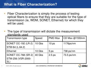
Characterization of Carbon Fiber and Glass Fiber Fabrics by Drape Fixture. By: Aaron Holmberg. Scope of Project . The following parameters must be determined through experimentation Force needed to deform fabric in shear related to the fabric’s characteristics

E N D
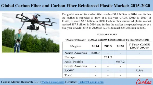
Characterization of Carbon Fiber and Glass Fiber Fabrics by Drape Fixture By: Aaron Holmberg
Scope of Project • The following parameters must be determined through experimentation • Force needed to deform fabric in shear related to the fabric’s characteristics • Locking Angle: The angle at which the shear force increases rapidly and the fabric begins to wrinkle related to the fabric’s characteristics • Determining these characteristics will help in predicting the drapability / formability of these fabrics which is useful knowledge when determining manufacturability of curved components with a particular fabric
Fixture Design • A fixture was designed to help determine the lock angle and force vs. fiber angle of fabrics • Fabric is clamped between two ridged steel plates • A rubber gasket was used between the plates to distribute clamping force evenly along the fabrics edge • Universal ball transfer unit (not pictured) were attached to the side of the bottom clamp to reduce friction on the glass guides (shown in green) during shearing test. • Dowel pins were install on the bottom clamp for alignment and tensile fiber attachment point.
Fixture Design • The back was cut out to allow for convective heat transfer during tested performed in the oven • The simple design allowed most of the fixture to be build at Sicomp
Installation of Fabric • Tip fixture on its side • Lay spacers into place
Installation of Fabric • Lay fabric blank and tensile fiber into place with a sheet of glass on top of fabric to eliminate fabric wrinkles • Clamp jaws are set in place and tightened while holding the bottom clamp edge against the spacer
Installation of Fabric • Flip fixture upright • Remove spacers • Set guide in place
Experiments • Various fabrics were cut into 200mm x 210mm pieces • After installing the fabric sample, an incremental increase of tension was applied by adding weights to a receptacle attached to the tensile fiber • The lower jaw displacement was measured by hand after each incremental increase in tension
Fabrics Tested • Five different fabrics were loaded into the fixture. • Devold AMT - glass fiber 90o • Sigmatex - carbon fiber 90o Light 0o glass fiber weave • CS-Interglass 0o-90o small tight weave • Sparas till VAC - carbon fiber 0o-90o heavy weave • No Label - carbon fiber 0o-90o light loose weave Additional information on these fabrics can be found in the table at the end of this Power Point presentation
Results • Devold AMT - glass fiber 90o • Very stiff during loading • Instantaneous wrinkling • No load data taken because of wrinkling
Results • Sigmatex - carbon fiber 90o light 0o glass fiber weave • Little resistance to shear • No locking angle found • No wrinkling experience at higher angles • Fiber compression at higher angles created fabric thickening without wrinkles of the fabric • Louver fiber formations were observed in the fabric near the clamps
Results • Photo of Louvers observed during experiment • Fibers would rotate out of plane only near the clamping surfaces
Results • No Label - carbon fiber 0o-90o light loose weave • First fabric tested • Load was incrementally applied and displacement measured • Tensile fiber was 317mm long at 0mm displacement which created large variations in tensile angle (angle of tensile fiber relative to horizontal) as displacement was increased due to a fixed pivot point • Tensile angle was compensated for in calculations found in Excel file • Future experiments were performed with a longer tensile fiber (1.920m) do decrease angle variation • Experimental results were inconclusive due to inaccuracy of measuring by hand and variation in tensile angle
Results • CS-Interglass 0o-90o small tight weave • The only fabric tested with a significant historysis • Historysis could be related to a combination of relatively greater friction between GF compared to CF and / or the tighter weave constricting sliding motion between fibers • Load incrementally applied and displacement measured • Locking angle determined to increase with greater tension on fabric as shear is applied • It is assumed low angle wrinkles are related to the friction between fibers overcoming tension applied by the weight of the lower clamp jaw • Additional downward force applied to the lower clamp jaw by hand allowed greater angles to be reached before fabric wrinkled
Results • With 7.9 Newtons of downward force due to the weight of the lower clamp jaw a locking angle of 9 degrees was found • When additional downward force was applied by hand to the lower clamp jaw a locking angle of 16 degrees was found • The locking angle is defined as the point just before wrinkles are observed
Results • Sparas till VAC - carbon fiber 0o-90o heavy weave • Binder was removed from this fabric by placing it in an oven at 400 C for two hours • Shear force was incrementally increase and displacement measured • Wrinkles were observed at approximately 50 degrees
Results • 0-90 Heavy Carbon Fiber – Tensile Force vs. Fabric Angle • Note: Tensile angle is not compensated for in the graph below
Additional Equipment Desired • More accurate data could be gathered using the following equipment in parallel with the drape fixture • Variable speed linear actuator with 200mm of travel and 20 N of force • 20 N load cell • Linear displacement transducer • Hand measurements proved to be extremely inaccurate
Conclusion • Additional testing will be needed before good fabric characterization results can be gathered • Fixture was proven to have potential in testing 0-90 woven fabrics. • Variation of lock angle results relative to fabric tension may be a concern in future experiments • Compensation for tensile angle resulted in questionable calculation results hens why it was excluded from the graph • Uncertainty may be associated with louvers observed near clamp surfaces. Additional testing may be needed to determine its effects.