Download
1 / 17
170 likes | 297 Views
Presenting: Capacitors. Michael Chiang EECS 713 12/05/2013. Objective:. Lab exercise for Capacitors Understand bypass/decoupling capacitor selection. Calculate the capacitors for specific rise time/knee frequency of a HSDC. Measure characteristics of capacitor. What is a capacitor?.

E N D
Presenting: Capacitors Michael Chiang EECS 713 12/05/2013
Objective: Lab exercise for Capacitors Understand bypass/decoupling capacitor selection. Calculate the capacitors for specific rise time/knee frequency of a HSDC. Measure characteristics of capacitor
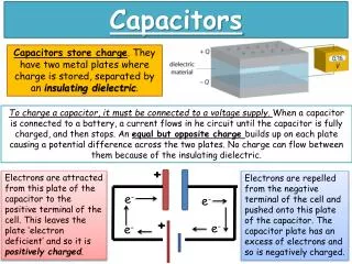
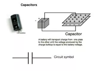
What is a capacitor? Capacitor is a two terminal electrical component used to store electric charge with conductors separated by an insulator.
Capacitor Applications: Capacitors are used in applications such as energy storage, power systems, noise suppression and coupling. In a high speed digital device, capacitors are used for uniform voltage distribution (bypass) and shunt current to the return path (decoupling) to provide low impedance path between power and ground or ground connections between gates. Every capacitor has a parasitic series inductance (lead inductance, package inductance, or mounting inductance – ESL), parasitic series resistance (equivalent Series resistance – ESR) which is real impedance, and self-resonate frequency (SRF):
Circuit Issues For uniform voltage distribution, a shunt capacitor is connected to the power supply in the frequency range where wired inductance can be a problem. This bypass capacitor provides low impedance between ground and power plane. Bypass capacitor loses effectiveness at high frequency where it becomes inductance. This problem is resolved by an assortment of capacitors (large and smaller) used to provide low impedance power source for every logic device across various operating frequency range.
Measuring Capacitor Characteristics Using Test Jig Using Impedance Analyzer
Test Jig Setup • Materials • Oscillocope: Tektronix DPO 4054 • Pulse Gen: SYSTRON 101 Pulse Generator • Resistors: • 100Ω, 0805, 1% • 10Ω, 0805, 1% • Capacitor: • 1µF, 0603, X5R, 10V • Cu Board • Analyzer Probes
Test Jig: Lead Inductance Rs = source resistance of test jig, Ω = 4.35Ω A = area under spike, Vs = 844.5pVs ∆V = Open-circuit Step Voltage of test jig, V = 0.996V L = lead inductance, H • Open Circuit test • Load: 1µF Capacitor
Test Jig: ESR Rs = source resistance of test jig, Ω = 4.35Ω X = measured step voltage after spike, V = 0.064V ∆V = Open-circuit Step Voltage of test jig, V = 0.996V
Test Jig: Capacitance ∆V = Open-circuit Step Voltage of test jig, V = 0.996V Rs = source resistance of test jig, Ω = 4.35Ω X = measured step voltage after spike, V = 0.064V dV/dt = charge rate of ramp, V/s = 0.236V/998ns = 236472.9V/s C = capacitance, F
Impedance Analyzer: Resonance Frequency • Materials • Impedance Analyzer: HP 4194A • Bread board • Capacitors: • 0.1µF, 0603, X7R, 16V • 1µF, 0402, X5R, 10V • 1µF, 0603, X5R, 10V • 10µF, 0603, X5R, 6.3V
Resonance Frequency: When the frequency is below the SRF it behaves capacitive. When the frequency is above the SRF it behaves inductively. The inductance in systems induces voltage change between the logic components and supply or ground plane that introduces noise. Therefore, a capacitor selected must behave capacitively.
1µF Ceramic Capacitor (0603) From Test Jig From Impedance Analyzer
Reference: Johnson, Howard, et al. “High Speed Digital Design: A Handbook of Black Magic” . Pearson Education, New Delhi, 1993, p253-255 & 275-299. http://www.farnell.com/datasheets/1525783.pdf http://people.eecs.ku.edu/~callen/713/713_Vias-F13.ppt