Download
1 / 34
370 likes | 530 Views
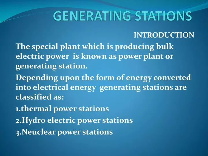
GENERATING STATIONS. INTRODUCTION The special plant which is producing bulk electric power is known as power plant or generating station. Depending upon the form of energy converted into electrical energy generating stations are classified as: 1.thermal power stations

E N D
GENERATING STATIONS INTRODUCTION The special plant which is producing bulk electric power is known as power plant or generating station. Depending upon the form of energy converted into electrical energy generating stations are classified as: 1.thermal power stations 2.Hydro electric power stations 3.Neuclear power stations
What is HEP HEP (Hydroelectric Power) is an environmentally friendly way to generate electricity.
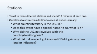
How it works A dam is built to trap water, usually in a valley where there is an existing lake.Water is allowed to flow through tunnels into the dam,to turn turbines and thus drive generators.Notice that the dam is much thicker at the bottom than at the top,because the pressure of the water increases with depth.
Water in dam (P.E.) Generator (Electrical) Nozzle (K.E.) Turbine (M.E.) Hydroelectric Power Plant Energy conversion in hydroelectric power plant
DAMDams are structures built over rivers to stop the water flow and form a reservoir The reservoir stores the water flowing down the river. This water is diverted to turbines in power stations.
SPILLWAYA spillway as the name suggests could be called as a way for spilling of water from dams. It is used to provide for the release of flood water from a dam. It is used to prevent over toping of the dams which could result in damage or failure of dams
PENSTOCK AND TUNNEL Penstocks are pipes which carry water from the reservoir to the turbines inside power station. They are usually made of steel and are equipped with gate systems. Water under high pressure flows through the penstock. A tunnel serves the same purpose as a penstock. It is used when an obstruction is present between the dam and power station such as a mountain.
SURGE TANKSurge tanks are tanks connected to the water conductor system. It serves the purpose of reducing water hammering in pipes which can cause damage to pipes. The sudden surges of water in penstock is taken by the surge tank, and when the water requirements increase, it supplies the collected water thereby regulating water flow and pressure inside the penstock.
POWER STATIONPower station contains a turbine coupled to a generator. The water brought to the power station rotates the vanes of the turbine producing torque and rotation of turbine shaft. This rotational torque is transferred to the generator and is converted into electricity.
POWER STATIONCONTD The used water is released through the tail race. The difference between head race and tail race is called gross head and by subtracting the frictional losses we get the net head
Once the dam is built,the energy is virtually free Water can be stored above the dam ready to cope with peaks in demand much more reliable than wind,solar or wave power No waste or pollution produced Electricity can be generated constantly Hydro-electric power stations can increase to full power very quickly unlike other power stations Advantages
disadvantages The dams are very expensive to build,however many dams are also used for flood control or irrigation,so building costs can be shared Building a large dam will flood a very large area upstream,causing problems for animals that used to live there Finding a suitable site can be difficult - the impact on residents and the environment may be unacceptable. Water quality and quantity downstream can be affected, which can have an impact on plant life.
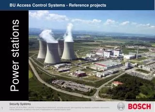
Steam power plants • The generating station which convertes heat energy of coal combustion into electrical energy is known as thermal power station . • Steam is produed in the boiler by utilising the heat of coal combustion.steam is then expanded in the prime mover and is then condensed in the condenser to be fed into the boiler again. The steam turbine drives the alternator which converts mechanical energy of the turbine into electrical energy.
Major components of steam power plants are 1.Coal and ash handling plant 2.Steam generating plants(boiler,economiser,superheater,airpreheater) 3.Steam turbine 4.Alternater 5.Feed water 6.Cooling arrangement
Coal handling system • it consists of a coal storage unit ,where coal is stored in bulk. Clean and dry coal is then transported through conveyor system for further processing in the crusher .crushing and pulverization of coal is important to reduce the size of particles for effective combustion. • Boiler • The heat of combustion of coal is utilised to convert water into steam at high temperature and pressure. • Super heater • The steam produed in the boiler is wet and is passed through the superheater where it is dried and superheated by the flue gases by their way to chimney.
Economiser • It extracts a part of heat from the flue gases to increase the temperature of feed water before supplying to the economiser. • Air preheater • It extracts a part of heat from the flue gases to increase the temperature of air used for coal combustion before supplying to the boiler. • steam turbine • The dry and superheted steam is fed to the steam turbine .the heat energy of steam is when passing over the blades of the turbine is converted into mechanical enegy(kinetic). After giving heat energy ,the steam is fed to the condenser .
Alternator • The steam turbine is coupled to an alternator. It converts mechanical energy of the turbine into electrical energy . • Feed water • The condensate from the condenser is used as feed water in the boiler. • Cooling tower • The hot water from the condenser is passed through the cooling tower where it is cooled
The schematic diagram of neuclear power plant is shown in fig.the whole arrangement can be divided into four main sections • 1.neuclear reactor • 2.heat exchanger • 3.steam turbine • 4.Alternator neuclear reactor it is an apparatus in which neuclear fuel like u235 subjected to neuclearfission.it houses the the fuel rod of uranium ,moderator (graphite rod)and control rod(cadmium) .
Heat exchanger • The coolant gives up heat to the heat exchanger which is utilised in raising the steam. • Steam turbine • The steam produced in the heat exchanger is fed to the steam turbine .the heat energy of steam is when passing over the blades of the turbine is converted into mechanical enegy(kinetic). After giving heat energy ,the steam is fed to the condenser . • Alternator • The steam turbine is coupled to an alternator. It converts mechanical energy of the turbine into electrical energy .
Feed water • The condensate from the condenser is used as feed water in the boiler. • Cooling tower • The hot water from the condenser is passed through the cooling tower where it is cooled
There are two systems of tapping from the mains • 1.tree system • 2.distributed system In tree system sub circuits are tapped from the main circuits at some convenient place .now a days this system is out of practice. Advantages The length of the cable required for the installation of wiring is less. So the initial cost is less . Disadvantages Fuses in the installation are scattered and location of the fault is not easy. • Voltage available at different points of load will vary. • Appearance of the system isnot so good.
Distribution system this system is most commonly used.in this system the main distribution circuit is brought to one or more distribution boxes from where it is further distributed to different branch circuits. Advantages 1.Fault finding is easy 2.The voltage available at different points of the circuit will be the same 3.Extension of the circuit is easy Disadvantages The length of the cable required for the installation of wiring is more. So the initial cost is more .