Download
1 / 33
340 likes | 792 Views
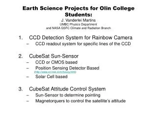
CCD Camera for Small Satellites . Andy Millard Neill Bryant Beltran Spring 2008. Objective. Develop CCD camera for CubeSat Design Parameters High sensitivity Low noise Physically reconfigurable. Block Diagram Design and Testing Printed Circuit Board Fabrication. Hardware.

E N D
CCD Camera for Small Satellites Andy Millard Neill Bryant Beltran Spring 2008
Objective Develop CCD camera for CubeSat Design Parameters High sensitivity Low noise Physically reconfigurable
Block Diagram Design and Testing Printed Circuit Board Fabrication Hardware
Block Diagram Computer DC Supply Timing Generator A/D DAQ Clock Decimator CCD Drivers Amplifier CCD
DC Supply 12 DC voltages required +15V and -10V supplied Desired voltages obtained from resistive network and buffered
CCD Sensor Kodak KAF-402 768x512 pixels (0.4M) 9x9μm pixel size Onboard amplifier Output sensitivity: 10μV/e Saturation signal: 100,000 electrons = 1V
Timing Generator Kodak KSC-1000 timing generator chip Generates all the timing signals necessary to run Kodak CCD sensors Capable of binning pixels and precise pixel timing Programmable over three-wire interface 56-pin MLF package
Clock Decimator Minimum pixel frequency of timing generator is 4.13MHz Desired pixel frequency is ~40kHz Solution: A CMOS counter on the timing chip outputs to slow the output clocks
CCD Drivers • The timing chip outputs cannot drive the CCD directly • Analog Devices ADG3123 translates the CMOS logic signals to arbitrary voltages
Amplifier Circuit The CCD output signal is amplified to take advantage of the full ADC input range A non-inverting op-amp topology was used Capacitively coupled to CCD output Low-noise JFET op-amp (TL071) Theoretical Gain: 2.47 V/V Theoretical Output Noise: 5.63μV Measured Gain: 2.44 V/V
Analog to Digital Converter Analog Devices AD7661 100 kSps 16-bit resolution 0V-2.5V single-ended input Parallel and serial interfaces Very reconfigurable 48-pin LQFP
DC Supply Test Circuit was tested on a bread board, then on the PCB All of the required voltages were within spec
Clock Decimator Testing • Input (Top) • 0V to 5V • 5MHz • Output (Bottom) • 0V to 5V • 37kHz
CCD Driver Testing • Input (Top) • 0V to 5V • 40kHz • Output (Bottom) • -4V to 6V • 40kHz
PCB Fabrication Circuit schematic and board layout done in EAGLE Surface mount component footprints had to be created 2-layer board with 7mil minimum line/space Advanced Circuits used for fabrication Mark Smart assisted by attaching SMD components
Objective: Create a system to retrieve and analyze the data from the Analog to Digital Converter. Method: Reverse Engineering. Software
Analysis Processing Reading Configuring Reverse Engineering MaxIm MATLAB LabVIEW
MaxIM Noise Analysis Dark Current / Thermal (T) Readout Noise (R) Ignore Background (B) and Source (S) Analysis
MATLAB Input: File of comma separated values Width of the output image Height of the output image Output: 16 bit .png file to be analyzed by MaxIm Processing
LabVIEW Input: 40 kHz data clock Data Output: File of comma separated values for MATLAB Reading
LabVIEW Timing Generator Interface SLoad: needs to stay hi until data is being written out. SData: data to be written. SClk: clock signal. Configuring
Serial data: 5 Vpp, 2.5 Vdc, 400 kHz sine wave. Serial clock: 5 Vpp, 2.5 Vdc, 40 kHz square wave. 128x128 pixel image. Testing Set Up
Results • 20x20 pixel sampling area or 400 pixels • =18390.930 • High noise, but the input signal was essentially noise, not the actual data from the CCD.
Analog to Digital Converter • SClk output observed at 80 kHz. • SDout was well conditioned. • LabVIEW could not observe the SClk output from the ADC and would time out. • SClk output width was too small for the DAQ.
Successes Workable architecture developed Most major subsystems functional DC supply, clock decimator, amplifier circuit, and CCD drivers all tested PCB fabricated Processing a file of pixel values into an image for analysis Reading and saving data with an external clock
Challenges Timing generator was never successfully mounted on board due to an error in the footprint ADC output not yet successfully read to computer Clock decimator approach to slowing down the timing generator outputs makes programming more difficult
Recommendations More modular design and testing Evaluation boards SMD prototyping boards Better understanding of timing generator and ADC will enable integration into the system
System read-out noise Use different integration times. Plot the standard deviation versus time, should be linear. Fit a linear equation to the points. Y-Intercept = Read-Out Noise. Slope = Dark Current. Testing Recommendations
Thank You Questions?