Download
1 / 39
390 likes | 586 Views
SGH-E710 SERVICE TRAINIG. R&D Group 3, Mobile Comm. Div. Samsung Electronics. CONTENTS. General Information Block Diagram and Schematics Circuit Description Phone test - Autocal, Repair PGM. Power Levels and Waveforms on PBA Troubleshooting Guide (Refer to SVC Manual).

E N D
SGH-E710SERVICE TRAINIG R&D Group 3, Mobile Comm. Div. Samsung Electronics
CONTENTS • General Information • Block Diagram and Schematics • Circuit Description • Phone test - Autocal, Repair PGM. • Power Levels and Waveforms on PBA • Troubleshooting Guide (Refer to SVC Manual)
General Information(1) • Frequency range: SGH-E710 DUAL MODE • Channel bandwidth: 200kHz • Fundamental frequency:13MHz • Intermediate frequencies : Near Zero IF(100KHz)
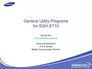
General Information(2) ■ Solution : - BB : Agere system(Lucent technology) - RF : SILAB. AERO 1CHIP / RFMD PAM ■ Design : - Dual folder camera INTENNA ■ LCD : 128 x 160, 65K TFT COLOR LCD ■ Memory : RD38F3350WWZDQ (256X64) ■ Function : GPRS Class 8, WAP etc.
General Information(5) • The chipset for E710 • Trident : Baseband main processor • CSP : Conversion signal processor • PSC2106 : Power Management IC • RD38F3350WWZDQ : 256M Flash/64M SRAM • RF3140 : PAM (included APC algorism) • Aero Transceiver(SI4205)
CSP Top View of SGH-E710 IRDA TRIDENT MEMORY CSP2106 PAM SIM CONN FEM SI4205 13MHz VC_TCXO PMIC
Circuit Description(1) • Antenna -INTENNA • Transmitting and Receiving the information desired from air interface. • RF Test Switch (CN400) • This is for adjusting and testing the handset in conjunction with the test equipment such as HP8922M or HP8960. • ANT Switch Diplexer (F400) • It operates such like a combination of Rx filter and Tx filter, and provides agreeable isolation between Tx and Rx.
Circuit Description(2) 3.1ANT Switch Diplexer LOGIC
Circuit Description: Rx(1) 1.RF Rx SAW Filter (GSM,DCS→F403,F402 PCS→F401 (but, not used)) It has the bandwidth of Rx frequencies, and suppresses interferers which can do affect the IF signal.
Circuit Description: Rx(2) 2. Si4205(U401) This chip integrates three differential-input LNAs (GSM or EGSM,DCS,PCS). IF SAW filter, RF VCO module, more than 70 other discrete components. The LNA inputs are matched to the 150 ohm balanced output SAW filters through external LC matching network. Image-reject mixer down-converts the RF signal to a 100 KHz intermediate.
Circuit Description: Rx(2) Frequency (IF) with the RFLO from frequency synthesizer. The RFLO frequency is between 1737.8 ~ 1989.9 MHz, and is internally divided by 2 for GSM850 and EGSM900 modes. The mixer output is amplified with an analog programmable gain amplifier(PGA), which is controlled by AGAIN[2:0] bit in register. The quadrature IF signal is digitized with high resolution A/D converts (ADCs).
Circuit Description: Rx(2) The SI4205 down-converters the ADC output to baseband with a digital 100KHz quadrature L0 signal. Digital decimation and IIR filters perfome channel selection to remove blocking and reference interface signals. After channel selection, the digital output is scaled with a digital PGA, which is controlled with the DGAIN[5:0] bit in register. DACs drive a differential analog signal onto the RXIP,RXIN,RXQP,RXQN pins to interface to standard analog- input baseband IC.
Circuit Description: Local(1) 1.VC-TCXO (OSC400) 13MHz fundamental frequency for PLLs and Baseband chipset (U303).
Circuit Description: Tx(1) 1. TX I,Q modulator Through SI4205 Tx I and Q signals (68KHz) are combined and up_converted to each TX frequency. I, Q voltage levels are 1Vp-p, respectively.
Circuit Description: Tx(2) 2. PAM (U400) We use a Power Control Chip Intergated on PA Module. This device is self-contained with 50 ohm input and output terminal. This device consists of Power amplifier and APC(Auto Power Control) circuit. The device is designed for use as the final RF amplifier in GSM850, EGSM900, DCS and PCS hand-held digital cllular equipment. On-board power dontral provides over 50dB of control range with an analog voltafe input; and, power with a logic “low” for standby operation.
Circuit Description: Tx(2) 2.1 Power on Sequence
Circuit Description: Logic • TRIDENT (U303) • Baseband Engine • Includes the DSP16000 core, ARM7TDMI microcontroller core,and a standard sets of peripherals for the DSP and ARM • communicates with Memory, Keypad, LCD, and other peripherals • DSP RAM :20k x 16 • DSP ROM : 144k x 16 • ARM RAM : 2k x 32 RAM(byte writable) • ARM ROM : 4k x 32 ROM(mask-programmable) • Processor Interface memory : 512 x 16 shared RAM
Circuit Description: Logic TRIDENT (U303) • ARM7TDMI 32-bit microprocessor : main call processing. • 32.768kHz X-tal Oscillator : the sleep mode • The interface circuitry : reset circuit, address bus (A0-A20), data bus (D0-D15), control signals (CP_WEN, CP_OEN, EAR_EN, LED_CTL, etc), GPIOs, and the communication ports. • Communication ports : UART1 and 2, the JTAG etc. • UART1 supports HP equipment interface, down loading, and data service. • UART2 and the JTAG are used for the software debugging.
Circuit Description: Logic CSP 1093 (U307) • Baseband radio and voiceband audio interfaces • Baseband receive path • Buffer, 10-bit ADC, PGA • Baseband transmit path • Transmit buffer, GMSK modulator, 9-bit DAC • ADC and DACs for Radio and Monitoring • 10-bit ADC for sampling RSSI, TXP, and etc • Voiceband Receive Path :speaker , mic • Event timing and control register • To control both B/B receive and B/B transmit activity • Power ramping control
Circuit Description: Logic PMIC(PSC2106:U100) • Includes seven low-dropout voltage regulator • LDO1-1.8v, LDO2:VCCD, LDO3:Vrf • LDO4-Vpac,LDO5:Vosc • LDO6:VCCA, LDO7:VCCB • VRTC • 250ms system reset generator • To ensure proper initialization of the system controller • 12bit monotonic DAC • Pwr_sw1(active low),Pwr_sw2(active high)
Circuit Description: Logic Memory This systems use INTEL’s Multi-Chip memory (RD38F3350WWZDQ). It is consist of 256M bits flash memory and 64M bits SRAM. 16 bit data line, D[0~15] ,22 bit address lines, A[1~22] which are connected to Trident (U303), LCD and camera controller(U200) and CSP1093 and sound generator (U202). They use 3 volt supply voltage, V_ccd and 1.8 volt supply voltage, Vcc_1.8a in the PSC2106.
Circuit Description: Logic Memory • The two flash memory block(128M+128M) and SRAM block are controlled via multiple chip enable (CP_CSROMEN, CP_CSROM2EN and CP_CSRAMEN) and output enable(CP_OEN and CP_WEN) signals generated by Trident II. • During wrting process, CP_WEN is low and it enables writing process to flash memory and SRAM. In contrast, during reading process, CP_OEN is low and it enables reading process from the flash memory or SRAM. • Memories use MEM_RST. And A(0) signal enavles lower byte of SRAM and UPPER_BYTE signal enables higher byte of SRAM.
Test Interface Jig TEST CABLE SERIAL CABLE TEST JIG POWER SUPPLY CABLE
Auto calibration Program Setting E3632A HP GPIB CABLE We need GPIB CABLE , RF CABLE, CALL BOX Etc….. RF CABLE Power Supply Cable S+ S-
Auto calibration Processing(2) FIRST: BATT CAL !!! SECOND : AUTO CAL!!!
Auto calibration Processing(3) Click~!
Repair Program Setting(cal saetting same) E3632A HP GPIB CABLE We need GPIB CABLE , RF CABLE, CALL BOX Etc….. RF CABLE Power Supply Cable S+ S-
Test Information • Test Equipment is HP8960 or CMD55 or CMU200. • Mode : Test mode • (Tx : BCH+TCH, Rx : CW generator) • Tx power level pass/fail limit have to be modified to allow calibrated Tx power levels of SGH-S100
Power Level & Voltage Waveform Rx Chain – Analog: Measurement Environment Test Mode Cont Rx on HP Setup: RF Generator Screen RF input = -50dBm, RF Gen Freq = 947MHz, (Channel is 60) RF Gen Band =GSM
Power Level & Voltage WaveformTx Chain • Active Cell mode • HP Setup RF input = -50dBm, TCH Channel = 60CH RF Gen Band = GSM
REPAIR PROGRAM SELECT BAND SELECT TCH CH CHANGE DAC VALUE SELECT MODE SELECT MODEL INPUT RX LEVEL
REPAIR PROGRAM CLICK~! (1) CLICK~! (2)
REPAIR PROGRAM TX: Measurement equipment RX : PBA ABOUT->VIEW ID:root P/W:tl_lee Tx/Rx SELECT