Download
1 / 24
320 likes | 575 Views
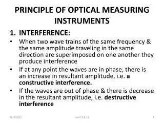
Optical Instruments. Physics 2415 Lecture 34 Michael Fowler, UVa. Today’s Topics. The lensmaker’s formula Magnifying power Lens combinations: ray tracing, telescopes. Refraction at a Spherical Surface. P. h. C. I. O.

E N D
Optical Instruments Physics 2415 Lecture 34 Michael Fowler, UVa
Today’s Topics • The lensmaker’s formula • Magnifying power • Lens combinations: ray tracing, telescopes.
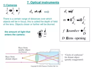
Refraction at a Spherical Surface P h C I O • Rays close to the axis (“paraxial”) will focus to an image inside the glass: • From we can show that R air glass do di
The Lensmaker’s Formula(optional derivation, if you’re curious) • The formula also works in reverse. A ray coming from an object in the glass will satisfy • For a convex lens with surfaces of radii R1, R2, the rays on going through R1 will converge (inside the glass) towards a point d1 such that . • But those rays don’t get there—they first meet surface R2, which focuses them in air to a point di, say, these rays being from a virtual object at d1, so the object distance is –d1, the final image is at di: • Adding the boxed formulas gives:
The Lensmaker’s Formula • This formula also works for plano convex lenses (one side flat, meaning R infinite) or if one or both sides are concave—but for concave sides, R must be taken negative. • Note: sometimes this formula is written with a minus sign—in those books, the rule is that R is taken positive if its center of curvature over is to the right. It’s a matter of taste.
Image Location by Ray Tracing • The rules we use for thin lenses: • We take the ray through the center of the lens to be undeflected and unshifted. • For a convex lens, rays passing through a focus on one side are parallel to the axis on the other side. • For a concave lens, rays coming in parallel on one side are deflected so they apparently come from the focal point on that same side.
Ray Tracing for a Thin Convex Lens O´ B di - f ho f F I A O di do We choose the ray through the lens center, a straight line in our approximation, and the ray parallel to the axis, which must pass through the focus when deflected. They meet at the image. hi From the straight line through the center, from the line BFI´ (and similar triangles!), I´ This gives immediately:
Convex Lens as Magnifying Glass • The object is closer to the lens than the focal point F. To find the virtual image, we take one ray through the center (giving ) and one through the focus near the object ( ), again but now the (virtual) image distance is taken negative. hi hi ho do f - do f di F
Definition of Magnifying Power • Mis defined as the ratio of the angular size of the image to the angular size of the object observed with the naked eye at the eye’s near point N, which is ho/N. • If the image is at infinity (“relaxed eye”) the object is at f, the magnification is (ho/f )/(ho/N) =N/f. • Maximum M is for image at N, then M = (N/f ) + 1. hi hi ho do f - do f di F
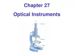
Simple and Compound Microscopes • The simple microscope is a single convex lens, of very short focal length. The optics are just those of the magnifying glass discussed above. • The simplest compound microscope has two convex lenses: the first (objective) forms a real (inverted) image, the second (eyepiece) acts as a magnifying glass to examine that image. • The total magnification is a product of the two: the eyepiece is N/fe, N = 25 cm (relaxed eye) the objective magnification depends on the distance between the two lenses, since the image it forms is in the focal plane of the eyepiece.
Diverging (Concave) Lens • The same similar triangles arguments here give from which provided we now take both di and f as negative! • . ho ho hi F di f – di f do
Formula Rules Updated… • The formula is valid for any thin lens. • For a converging lens, f is positive, for a diverging lens f is negative. • The object distance do is positive—unless, in a multi-lens system, the object is on the “wrong” side of the lens! (We’ll do an example.) • The image distance di is positive for a real image, negative for a virtual image.
Empty Lens 1) It will magnify 2) Things will look smaller 3) Things will look the same size A “concave lens” is actually made of very thin glass, is hollow and filled with air. How will this lens behave at close quarters under water?
Empty Lens 1) It will magnify 2) Things will look smaller 3) Things will look the same size A “concave lens” is actually made of very thin glass, is hollow and filled with air. How will this lens behave at close quarters under water?
Clicker Question • I have two identical thin convex lenses of focal length f. If I put them together ()(), what is the focal length of the combination? • 2f • f • f/2
Clicker Answer • f/2: the first lens refracts the rays towards a focus at f, they immediately encounter the second lens, which refracts them more, to a closer focus. • Important! The image from the first lens is the object for the second lens. • Combined focal length from formula: for the second lens, , the object is behind the lens! • From we have • .
Two Convex Lenses Separated • Easy example: two lenses, same focal length f, separated by f, so rays through the center of one lens are parallel to the axis after (or before) passing through the other lens: This would be the real image for lens A alone, it is the object for lens B. B A object image f
Further Separated… • If the first lens forms an image between the lenses, but less than the focal distance to the second lens, the combination produces a virtual image (this is the basic ray pattern for simple telescopes and microscopes): This is the real image from the first lens The ray shown purple is the one parallel to the axis between the lenses—so it passes through both foci outside the system This is the final virtual image: notice it’s upside down—that’s OK for astro telescopes.
Even More Separated… • If the separation is sufficient that the image from the first lens A is outside the focal length of lens B, there is a final realupright image beyond the second lens: B A We first locate the image from lens A, then draw in the ray from it through the center of lens B Notice the usefulness of the ray parallel to the axis between the lenses—it goes through the foci (white circles) outside.
The Spyglass • The real image from the two convex lenses can be viewed through a third, powerful, lens to make a telescope with upright image, better for terrestrial viewing (as opposed to astronomical uses).
Astronomical Telescope: Angular Magnification • Any object in astronomy can be taken to be at infinite distance: the relevant image size parameter is the angular size of the image. • Example: imagine pointing a telescope at Jupiter, so Jupiter’s south pole is on the axis of the telescope. • Rays coming from Jupiter’s north pole can be taken to be parallel and at a small angle to the axis on entering the telescope, so they form an image in the focal plane… A B fA
Astronomical Telescope: Angular Magnification • An “eyepiece” lens of shorter focal length is added, with the image from lens A in the focal plane of lens B as well, so viewing through B gives an image at infinity. • Tracking the special ray that is parallel to the axis between the lenses (shown in white) the ratio of the angular size image/object, the magnification, is just the ratio of the focal lengths fA/fB. A B fA fA fB fB
Galilean Telescope • The rays from the object lens are intercepted by a concave lens before they form an image. The concave lens is positioned so that the image would have been at its focus—so it forms a virtual image at infinity (from the lens formula). • The angular magnification is again the ratio of focal lengths. fB fB fA
The Eye Most of the focusing takes place at the cornea, filled with watery stuff. The lens shape is adjusted by muscles to make finer adjustments to the focusing.