Download
1 / 77
780 likes | 927 Views
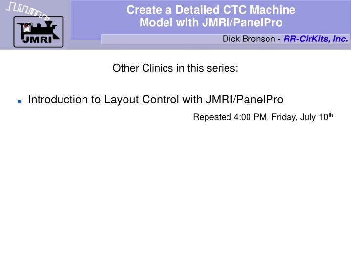
Create a Detailed CTC Machine Model with JMRI/PanelPro. Dick Bronson - RR-CirKits, Inc. Other Clinics in this series: Introduction to Layout Control with JMRI/PanelPro Repeated 4:00 PM, Friday, July 10 th. CTC. CTC Centralized Traffic Control

E N D
Create a Detailed CTC MachineModel with JMRI/PanelPro Dick Bronson - RR-CirKits, Inc. • Other Clinics in this series: • Introduction to Layout Control with JMRI/PanelPro Repeated 4:00 PM, Friday, July 10th
CTC • CTC Centralized Traffic Control • According to Wikipedia Centralized Traffic Control (CTC) is a signalling system used by railroads. The system consists of a centralized train dispatcher's office that controls railroad switches in the CTC territory and the signals that railroad engineers must obey in order to keep the traffic moving safely and smoothly across the railroad. • CTC systems are considered sufficient authority to run trains based strictly on signal indications. This is because CTC signals default to 'Stop' and require a human dispatcher to 'Clear' them. • The CTC panel depicted in this clinic is a Classic era US&S panel.
CTC • CTC basics • ABS defaults to 'Clear' signals, and drops to 'Stop' if the block immediately beyond the signal is occupied, or if the switch (turnout) beyond the signal is set against the direction of traffic.
CTC • CTC basics • ABS defaults to 'Clear' signals, and drops to 'Stop' if the block immediately beyond the signal is occupied, or if the switch (turnout) beyond the signal is set against the direction of traffic. • CTC is a layer superimposed over the basic ABS system to hold all signals in the 'Stop' aspect unless cleared by the dispatcher to their ABS value. This means that the local ABS logic will always (normally) supercede in the lower speed aspect. I.e. The dispatcher does NOT actually set the signals to green. He just permits them to go green.
CTC • CTC basics • ABS defaults to 'Clear' signals, and drops to 'Stop' if the block immediately beyond the signal is occupied, or if the switch (turnout) beyond the signal is set against the direction of traffic. • CTC is a layer superimposed over the basic ABS system to hold all signals in the 'Stop' aspect unless cleared by the dispatcher to their ABS value. This means that the local ABS logic will always (normally) supercede in the lower speed aspect. I.e. The dispatcher does NOT actually set the signals to green. He just permits them to go green. • 'Clear' to the dispatcher means proceed, one way only. 'Normal' to the dispatcher is all signals at stop.
CTC • CTC basics • This clinic assumes that you understand the ABS signal system previously covered because that is the basis for the CTC operation.
CTC • CTC basics • This clinic assumes that you understand the ABS signal system previously covered because that is the basis for the CTC operation. • We will attempt to cover the basic steps required for the CTC panel, continuing from where we left off with the SSL.
CTC • CTC basics • This clinic assumes that you understand the ABS signal system previously covered because that is the basis for the CTC operation. • We will attempt to cover the basic steps required for the CTC panel, continuing from where we left off with the SSL. • The completed 2009Clinic7.xml panel has indicators for all the required logic.
CTC • CTC basics • This clinic assumes that you understand the ABS signal system previously covered because that is the basis for the CTC operation. • We will attempt to cover the basic steps required for the CTC panel, continuing from where we left off with the SSL. • The completed 2009Clinic7.xml panel has indicators for all the required logic. • The 2009Clinic8.xml panel only includes prototypical indications, other than the traffic simulation toggles.
CTC • CTC basics • This panel is the one we left with at the end of the SSL section. It has relay sounds and delays between the block sensors and the panel indicators.
CTC • CTC basics • This panel is the one we left with at the end of the SSL section. It has relay sounds and delays between the block sensors and the panel indicators. • Open the Panel Editor and select 'Add Multisensor'.
CTC • CTC basics • This panel is the one we left with at the end of the SSL section. It has relay sounds and delays between the block sensors and the panel indicators. • Open the Panel Editor and select 'Add Multisensor'. • Drag the system items to the correct icon for each lever position, then click ;Add to Panel'.
CTC • CTC basics • Note: Here is the image showing all the variable names for Plant 5-6
CTC • CTC basics • This panel is the one we left with at the end of the SSL section. It has relay sounds and delays between the block sensors and the panel indicators. • Open the Panel Editor and select 'Add Multisensor'. • Drag the system items to the correct icon for each lever position, then click ;Add to Panel'. • Do the same for all 4 signal levers.
CTC • CTC basics • Now add the signal indicator lamps. Select 'Add Sensor' and set the icons to green jewels.
CTC • CTC basics • Now add the signal indicator lamps. Select 'Add Sensor' and set the icons to green jewels. • Then add: IS6:LDGK (Plant 6:Left proceeD siGnal indiKtor) and IS6:RDGK (Plant 6:Right proceeD siGnal indiKtor)
CTC • CTC basics • Now add the signal indicator lamps. Select 'Add Sensor' and set the icons to green jewels. • Then add: IS6:LDGK (Plant 6:Left proceeD siGnal indiKtor) and IS6:RDGK (Plant 6:Right proceeD siGnal indiKtor) • Move them into position.
CTC • CTC basics • Now add the signal indicator lamps. Select 'Add Sensor' and set the icons to green jewels. • Then add: IS6:LDGK (Plant 6:Left proceeD siGnal indiKtor) and IS6:RDGK (Plant 6:Right proceeD siGnal indiKtor) • Move them into position. • And repeat for plant 8, 10, and 12.
CTC • CTC basics • Now add the signal indicator lamps. Select 'Add Sensor' and set the icons to green jewels. • Then add: IS6:LDGK (Plant 6:Left proceeD siGnal indiKtor) and IS6:RDGK (Plant 6:Right proceeD siGnal indiKtor) • Move them into position. • And repeat for plant 8, 10, and 12. • Now change the icons to red jewels.
CTC • CTC basics • Then add: IS6:NGK (Plant 6:Normal siGnal indiKtor)
CTC • CTC basics • Then add: IS6:NGK (Plant 6:Normal siGnal indiKtor) • Move it into position.
CTC • CTC basics • Then add: IS6:NGK (Plant 6:Normal siGnal indiKtor) • Move it into position. • And repeat for plant 8, 10, and 12.
CTC • CTC basics • Then add: IS6:NGK (Plant 6:Normal siGnal indiKtor) • Move it into position. • And repeat for plant 8, 10, and 12. • Open the Logix table
CTC • CTC basics • Then add: IS6:NGK (Plant 6:Normal siGnal indiKtor) • Move it into position. • And repeat for plant 8, 10, and 12. • Open the Logix table • Add IX6:GC (Plant 6 siGnal Control
CTC • CTC basics • Then add: IS6:NGK (Plant 6:Normal siGnal indiKtor) • Move it into position. • And repeat for plant 8, 10, and 12. • Open the Logix table • Add IX6:GC (Plant 6 siGnal Control • Click 'New Conditional'
CTC • CTC basics • Then add: IS6:NGK (Plant 6:Normal siGnal indiKtor) • Move it into position. • And repeat for plant 8, 10, and 12. • Open the Logix table • Add IX6:GC (Plant 6 siGnal Control • Click 'New Conditional' • and name it 6GC Sound then 'Add State Variable'
CTC • CTC basics • Then add: IS6:NGK (Plant 6:Normal siGnal indiKtor) • Move it into position. • And repeat for plant 8, 10, and 12. • Open the Logix table • Add IX6:GC (Plant 6 siGnal Control • Click 'New Conditional' • and name it 6GC Sound then 'Add State Variable' • 'Sensor Active' IS6:NGL and 'Update Conditional'.
CTC • CTC basics • What we are doing is adding sound to the lever action.
CTC • CTC basics • What we are doing is adding sound to the lever action. • 'Play Sound File' on 'Change to False' the 'Signal-lever'
CTC • CTC basics • What we are doing is adding sound to the lever action. • 'Play Sound File' on 'Change to False' the 'Signal-lever' • We also need to play the sound of the lever restoring to normal.
CTC • CTC basics • What we are doing is adding sound to the lever action. • 'Play Sound File' on 'Change to False' the 'Signal-lever' • We also need to play the sound of the lever restoring to normal. • 'Play Sound File' on 'Change to True' the 'Signal-normal'
CTC • CTC basics • What we are doing is adding sound to the lever action. • 'Play Sound File' on 'Change to False' the 'Signal-lever' • We also need to play the sound of the lever restoring to normal. • 'Play Sound File' on 'Change to True' the 'Signal-normal' • 'Update Conditional' and we should have sound on the lever.
CTC • CTC basics • Now copy the Logix for IS8:GC, IS10:GC, and IS12:GC.
CTC • CTC basics • Now copy the Logix for IS8:GC, IS10:GC, and IS12:GC. • Then edit each entry to reflect the required new values.
CTC • CTC bell • Now copy the Logix for IS8:GC, IS10:GC, and IS12:GC. • Then edit each entry to reflect the required new values. • Go back to our panel. The CTC panel had a bell that rang every time a train entered an OS section. This was to alert the dispatcher of train movements in case he was away from the panel. However he was able to disable the bell.
CTC • CTC bell • Start by adding a plate for the bell cutout switch. 'Add Icon (plain)'
CTC • CTC bell • Start by adding a plate for the bell cutout switch. 'Add Icon (plain)' • Navigate to 'icons – USS – plate – misc' and drag the 'bell-cutout' image to the icon position, then 'Add to Panel'
CTC • CTC bell • Start by adding a plate for the bell cutout switch. 'Add Icon (plain)' • Navigate to 'icons – USS – plate – misc' and drag the 'bell-cutout' image to the icon position, then 'Add to Panel' • Move it into position near the bottom of the panel.
CTC • CTC bell • Start by adding a plate for the bell cutout switch. 'Add Icon (plain)' • Navigate to 'icons – USS – plate – misc' and drag the 'bell-cutout' image to the icon position, then 'Add to Panel' • Move it into position near the bottom of the panel. • Now select 'Add Sensor' and set the icon image to be a toggle switch.
CTC • CTC bell • Start by adding a plate for the bell cutout switch. 'Add Icon (plain)' • Navigate to 'icons – USS – plate – misc' and drag the 'bell-cutout' image to the icon position, then 'Add to Panel' • Move it into position near the bottom of the panel. • Now select 'Add Sensor' and set the icon image to be a toggle switch. • Add a sensor IS:AXR (Approach Bell Relay).
CTC • CTC bell • Move the toggle switch into position on the bell cutout plate
CTC • CTC bell • Move the toggle switch into position on the bell cutout plate • Now add a Logix and call it IX:AXC (Approach Bell Control)
CTC • CTC bell • Move the toggle switch into position on the bell cutout plate • Now add a Logix and call it IX:AXC (Approach Bell Control) • Create it.
CTC • CTC bell • Move the toggle switch into position on the bell cutout plate • Now add a Logix and call it IX:AXC (Approach Bell Control) • Create it. • Add a 'New Conditional'.
CTC • CTC bell • Move the toggle switch into position on the bell cutout plate • Now add a Logix and call it IX:AXC (Approach Bell Control) • Create it. • Add a 'New Conditional'. • and call it 'Switch Click'.
CTC • CTC bell • Move the toggle switch into position on the bell cutout plate • Now add a Logix and call it IX:AXC (Approach Bell Control) • Create it. • Add a 'New Conditional'. • and call it 'Switch Click'. • The variable is IS:AXR and we play 'toggle-on' when it goes 'true', and 'toggle-off' when it goes 'false'. Then 'Update Conditional'.
CTC • CTC bell • Now open 'Plant 5 OS Indicator'.
CTC • CTC bell • Now open 'Plant 5 OS Indicator'. • Edit the OS5 Bell entry.
CTC • CTC bell • Now open 'Plant 5 OS Indicator'. • Edit the OS5 Bell entry. • Add a new variable for the 'Bell Cutout' switch.
CTC • CTC bell • Now open 'Plant 5 OS Indicator'. • Edit the OS5 Bell entry. • Add a new variable for the 'Bell Cutout' switch. • Uncheck the trigger option for the switch so the bell does not ring if the switch is thrown. 'Update Conditional'