Download
1 / 69
730 likes | 976 Views
Designing Databases. 13. Systems Analysis and Design, 7e Kendall & Kendall. © 2008 Pearson Prentice Hall. Data Storage. The data must be available when the user wants to use them The data must be accurate and consistent Efficient storage of data as well as efficient updating and retrieval

E N D
Designing Databases 13 Systems Analysis and Design, 7e Kendall & Kendall © 2008 Pearson Prentice Hall
Data Storage • The data must be available when the user wants to use them • The data must be accurate and consistent • Efficient storage of data as well as efficient updating and retrieval • It is necessary that information retrieval be purposeful
Data Storage (Continued) • There are two approaches to the storage of data in a computer-based system: • Store the data in individual files, each unique to a particular application • Build a database • A database is a formally defined and centrally controlled store of data intended for use in many different applications
Major Topics • Databases • Normalization • Key design • Using the database • Data warehouses • Data mining
Databases • Effectiveness objectives of the database: • Ensuring that data can be shared among users for a variety of applications • Maintaining data that are both accurate and consistent • Ensuring data required for current and future applications will be readily available • Allowing the database to evolve as the needs of the users grow • Allowing users to construct their personal view of the data without concern for the way the data are physically stored
Reality, Data, and Metadata • Reality • The real world • Data • Collected about people, places, or events in reality and eventually stored in a file or database • Metadata • Information that describes data
Entities • Any object or event about which someone chooses to collect data • May be a person, place or thing • May be an event or unit of time
Entity Subtype • An entity subtype is a special one-to-one relationship used to represent additional attributes, which may not be present on every record of the first entity • This eliminates null fields stored on database tables • For example, students who have internships. The STUDENT MASTER should not have to contain information about internships for each student
Relationships • Relationships • One-to-one • One-to-many • Many-to-many • A single vertical line represents one • A crow’s foot represents many
Figure 13.2 Entity-relationship (E-R) diagrams can show one-to-one, one-to-many, or many-to-many associations
Figure 13.3 The entity-relationship symbols and their meanings
Entity Associative Entity Attributive Entity Entity
Figure 13.4 The entity-relationship diagram for patient treatment. Attributes can be listed alongside the entities. In each case, the key is underlined
Attributes, Records, and Keys • Attributes represent some characteristic of an entity • Records are a collection of data items that have something in common with the entity described • Keys are data items in a record used to identify the record
Key Types • Key types are: • Primary key – unique attribute for the record • Candidate key – an attribute or collection of attributes, that can serve as a primary key • Secondary key, a key which may not be unique, used to select a group of records • Composite key, a combination of two or more attributes representing the key
Metadata • Data about the data in the file or database • Describe the name given and the length assigned each data item • Also describe the length and composition of each of the records
Figure 13.7 Metadata includes a description of what the value of each data item looks like
Files • A file contains groups of records used to provide information for operations, planning, management, and decision making • Files can be used for storing data for an indefinite period of time, or they can be used to store data temporarily for a specific purpose
File Types • Master file • Table file • Transaction file • Report file
Master and Table Files • Master files • Contain records for a group of entities • Contain all information about a data entity • Table files • Contains data used to calculate more data or performance measures • Usually read-only by a program
Transaction and Report Files • Transaction records • Used to enter changes that update the master file and produce reports • Report files • Used when it is necessary to print a report when no printer is available • Useful because users can take files to other computer systems and output to specialty devices
File Organization • Sequential organization • Linked lists • Hashed file organization
Hashed File • 500 employees... Use ssn as the key. • Divide by prime number. • Example: • 053-46-8942 • Divide by 509 • = 15047 • Note 105047 x 509 = 53468923. That differs by 19. Store as 19.
Relational Databases • A database is intended to be shared by many users • There are three structures for storing database files: • Relational database structures • Hierarchical database structures • Network database structures
Figure 13.11 In a relational data structure, data are stored in many tables
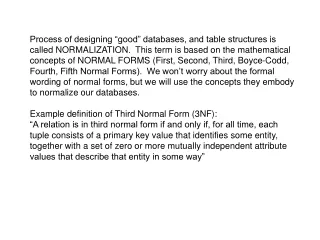
Normalization • Normalization is the transformation of complex user views and data stores to a set of smaller, stable, and easily maintainable data structures • The main objective of the normalization process is to simplify all the complex data items that are often found in user views
Figure 13.12 Normalization of a relation is accomplished in three major steps
Data Model Diagrams • Shows data associations of data elements • Each entity is enclosed in an ellipse • Arrows are used to show the relationships
Figure 13.15 Drawing data model diagrams for data associations sometimes helps analysts appreciate the complexity of data storage
First Normal Form (1NF) • Remove repeating groups • The primary key with repeating group attributes are moved into a new table • When a relation contains no repeating groups, it is in first normal form
Figure 13.18 The Original unnormalized relation SALES-REPORT is separated into two relations, SALESPERSON (3NF) and SALESPERSON-CUSTOMER (1NF)
Second Normal Form (2NF) • Remove any partially dependent attributes and place them in another relation • A partial dependency is when the data are dependent on a part of a primary key • A relation is created for the data that are only dependent on part of the key and another for data that are dependent on both parts
Figure 13.20 The relation SALESPERSON-CUSTOMER is separated into a relation called CUSTOMER-WAREHOUSE (2NF) and a relation called SALES (1NF)
Third Normal Form (3NF) • Must be in 2NF • Remove any transitive dependencies • A transitive dependency is when nonkey attributes are dependent not only on the primary key, but also on a nonkey attribute
Figure 13.22 The relation CUSTOMER-WAREHOUSE is separated into two relations called CUSTOMER (1NF) and WAREHOUSE (1NF)
Using the Entity-relationship Diagram to Determine Record Keys • When the relationship is one-to-many, the primary key of the file at the one end of the relationship should be contained as a foreign key on the file at the many end of the relationship • A many-to-many relationship should be divided into two one-to-many relationships with an associative entity in the middle
Guidelines for Master File/Database Relation Design • Each separate data entity should create a master database table • A specific data field should exist on one master table • Each master table or database relation should have programs to create, read, update, and delete the records
Integrity Constraints • Entity integrity • Referential integrity • Domain integrity
Entity Integrity • The primary key cannot have a null value • If the primary key is a composite key, none of the fields in the key can contain a null value
Referential Integrity • Referential integrity governs the nature of records in a one-to-many relationship • Referential integrity means that all foreign keys in the many table (the child table) must have a matching record in the parent table
Referential Integrity (Continued) Referential integrity implications: • You cannot add a record in the child (many) table without a matching record in the parent table • You cannot change a primary key that has matching child table records • You cannot delete a record that has child records
Referential Integrity (Continued) • Implemented in two ways: • A restricted database updates or deletes a key only if there are no matching child records • A cascaded database will delete or update all child records when a parent record is deleted or changed
Domain Integrity • Domain integrity rules are used to validate the data • Domain integrity has two forms: • Check constraints, which are defined at the table level • Rules, which are defined as separate objects and can be used within a number of fields
Anomalies • Data redundancy • Insert anomaly • Deletion anomaly • Update anomaly