Download
1 / 44
440 likes | 590 Views
Ground Based Observatories (GBO) Mission PDR. S. B. Mende S. Harris University of California - Berkeley. Overview. GBO PDR - Stewart Harris Introduction to GBO Requirements Science Objective Derived Requirements Implementation GBO Site Location and Design Design

E N D
Ground Based Observatories(GBO) Mission PDR S. B. Mende S. Harris University of California - Berkeley
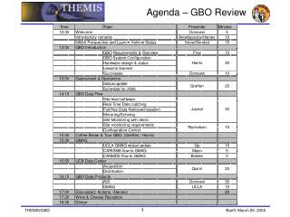
Overview • GBO PDR - Stewart Harris • Introduction to GBO • Requirements • Science Objective • Derived Requirements • Implementation • GBO Site Location and Design • Design • Instrument Design (ASI and GMAG) • Observatory Equipment • Deployment Plans and Status • Results from Engineering Peer Review • Canadian Collaboration – Eric Donovan
GBO Team Institutions • University of California – Berkeley (UCB) • S. B. Mende – GBO science lead • Provides ASI development, system engineering, GBO system fabrication and construction, data archive and dissemination • University of California – Los Angeles (UCLA) • C. T. Russell – magnetometer science lead • Develop and provide ground magnetometer for GBO / EPO • University of Calgary • E. Donovan – Canadian science lead • Providing GBO system deployment in Canada, field management, data collection, development participation • University of Alberta • I. Mann – magnetometer scientist • Providing access to Canadian magnetometer network
UCB Organization GBO / UCB Organization GBO Lead Co-Investigator S. B. Mende 510-642-0876 Administrator Ya Ling Zhu 510-643-5176 Project Manager S. Harris 510-643-3395 System Eng. S. Harris Mechanical G. Dalton Software S. Geller Test & Verif. H. Frey Electrical Test TBD Assembly B. Dalen
UCLA Organization GBO/EPO Magnetometer Organization Lead Co-Investigator C. T. Russell 310-825-3188 R & QA D. Dearborn 310-825-1488 Business Office J Nakatsuka 310-825-3939 Program Manager D. Pierce 775-588-0356 Magnetics R. Snare Analog D. Pierce Mechanical G. Barr Digital D. Dearborn Assembly W. Greer
GBOs: A synoptic view of the aurora Global auroral image taken by IMAGE WIC. Proposed THEMIS GBO sites superimposed.
GBO Science Objective GBO shall monitor the auroral light and ionospheric currents across North America in order to localize the time, location, and evolution of the auroral manifestation of the substorm. Themis mission requirement relating to GBO: Determine substorm onset time and substorm meridian magnetic local time (MLT) using All Sky Imagers (one ASI per MLT hr) and Ground Magnetometer (two GMAG per MLT hr) with t_res<30s and dMLT<6° respectively, in an 8hr geographic local time sector including the US. Note: dMLT < 6° is minimum requirement, while dMLT < 1° is baseline specification.
Implementation Requirements • GBO Program Implementation: • Integrate ASI from UCB, GMAG from UCLA with site prep and deployment provided by U. Calgary • Build, calibrate and qualify first unit within one year after start of Phase B • Five sites shall be installed two winters before THEMIS launch • Total GBO installed network shall be 20 sites, installed one winter before THEMIS launch
GBO Site Locations IMAGE FUV substorm onset identification.
Observatory Design • Major components: • Science Instruments: • All Sky Imager (ASI) • Ground Magnetometer (GMAG) • GPS • Observatory Equipment • Communications • Environment Control • System Computer
Internet GBO Components Iridium All Sky Imager GPS Telesat Dish Computer Enclosure GMAG AC Power • Variations possible at some sites: • Existing magnetometer • Enclosures not needed • Existing Internet connection
The Environment Summer and Winter USGS Tundra monitoring site Alaskan Tundra
Alaska (Poker Flat) Highest max: +35º C (1919) Lowest min: -54º C (1934) Normal max: +23º C (1 Jul) Normal min: -28º C (31 Jan) Southern Canada (Winnipeg) Highest max: +42º C Lowest min: -44º C Expected Temperatures “Reasonable” Design Range: -50º to +40º C
All Sky Imager • Overview: • Design • Specifications • Interface • Data Products
All Sky Imager Heritage • Environmental protection/deployment and automation drawn from AGOs (flawless multi-year operation in Antarctica). • Prototype camera field tested in Canada • Demonstrated high cadence, high sensitivity • Taking 5s images
ASI Enclosure External Construction Internal Construction Pipe Clamp Shown Design concept: Allison Park Group, Inc.
Sun Shade Design All Sky Lens Retracted(Fail-safe)Position Closed Position • Drivers: • ASI must survive, without degradation, non-operating exposure to daytime sun exposure • CCD is Sony Interline Transfer device ICX249AL • Features “microlens” on each pixel, an organic material subject to deterioration due to UV exposure • All Sky Lens uses Peleng Fisheye f/3.5 • A/R coating exhibited discoloration after one summer in Athabasca
ASI Specifications • Imager: • Field of View: 170º full angle • Spectral passband: 400 – 700 nm (with IR filter) • Sensitivity: < 1kR (5:1 S/N) • Spatial resolution: 290 pixel diameter all-sky-image • Exposure duration: programmable, 1 sec typical • Cadence: 5 s demonstrated, 3 s appears feasible • Enclosure: • Operate in external ambient –50º to +40ºC • Maintain internal temperature at 20º ± 10ºC • Requires about 150 W heating • Hermetically sealed unit w/ nitrogen purge • Dessicant used for field repair • Hermetically sealed electrical connectors • Polycarbonate/acrylic dome • Flexible mounting
ASI Electrical Interface • Electrical: • Two connectors: Data and Power • Physical: • Hermetically sealed, O-ring closure on housing • Stainless steel shell • Weatherproof
ASI Data Products • ASI primary image 290 pixel diameter is “binned” to 0.5° resolution (thumbnails) • Primary science data: • Stream #1 (~ 1kbps)(incl GMAG, housekeeping) • • Available via SAT comm, either Telesat (Internet real-time) or Iridium (daily) • High resolution data: • Stream #2 (180 kbps) • Selective downloads via Telesat/Internet • Periodic backups via disk swapping
ASI Data Products • ASI primary image 290 pixel diameter is “binned” to 0.5° resolution (thumbnails) • Primary science data: • Stream #1 (~ 1kbps)(incl GMAG, housekeeping) • • Available via SAT comm, either Telesat (Internet real-time) or Iridium (daily) • High resolution data: • Stream #2 (180 kbps) • Selective downloads via Telesat/Internet • Periodic backups via disk swapping
Ground Magnetometer • Overview: • Specifications • Design • Data Products • Software • GBO & E/PO
Magnetometer – GBO Design • Sub-System Features GPS Receiver Antenna and Electronics Integrated into one package May be located >30M from host (RS232 signals) NTP compatible (<1msec time accuracy) Flxugate Magnetometer ±72KnT dynamic range @ 0.03nT Resolution (~22 bits) Offset DAC system for 72 4KnT ranges per axis 2 Vectors per second data rate Low Power < 2W Small Size 22cm x 13cm x 5cm Ruggedized All Weather Sensor Design USB interface for data retrieval and firmware upload
GPS Receiver RS232 bidirectional Up to 30M cable length USB Interface GBO Data System RS232 bidirectional To Power Supply Power Control 12VDC Survival Heater and Thermistor Antenna Heater Up to 50M cable length GPS Power GMAG Interface To Fluxgate Sensor GMAG System Overview
GMAG Sensor • Ground Magnetometer Fluxgate Sensor ~100cm
GMAG Data Files • Data Inputs Include: Configuration File (UCLA_GBO_ssss_Vxx_xx.INI) uP Firmware File (UCLA_GBO_ssss_Vxx_xx.UPF) FPGA Firmware File (UCLA_GBO_ssss_Vxx_xx.GAF) • Data Outputs Include: Mag Vector Data (ssssdddddd_MAG_hh_cc.RMD) Mag Housekeeping Data (ssssdddddd_MAG_hh_cc.HKD) Magnetometer Log Data (ssssdddddd_MAG_hh_cc.LOD) Mag Calibration Data (UCLA_GBO_ssss_Vxx_xx.CAL)
GMAG Software • Magnetometer Setup using LabView Program Real time display of three axis time series data Real time display of three axis Power Spectra Operator control of Mag. settings (Heaters, Offset DACs, modes) • Autonomous Operations using C++ Program Command Line execution Initialization controlled via Configuration file
GMAG Deployment • UCLA Deliveries: • 20 Magnetometers: 10 E/PO, 8 GBO, 2 Spares • Schedule for GBO: • 1 prototype delivered Winter ‘03 • 5 in Fall ’04 • 5 in Fall ’05 • Schedule for E/PO: • 5 in Summer ’04 • 5 in Summer ‘05
Observatory Infrastructure • Overview: • Provides Data Collection • Data Access • Environmental Protection • Heating & A/C • Smart Power Control • Remote Intervention “Box within a Box” Internal Rack Mount for Equipment (Doubles as Shipping Case) External Insulated Environmental Enclosure (Provided where required)
Internal Components • Elements include: • Data collection computer H/W • Hot swap HDD (2) • Environment controller • Communications equipment • Telesat / Starband prime chan. • Iridium backup channel • Power conditioning
Requirements: Unattended operation minimum 4 mo/observing season Support digital I/F and data storage ASI & GMAG Provide GPS for time sync and location calibration Provide means for daily uplink of “Stream 1” data Total transfer requires about 3MB per day Shall store high resolution “Stream 2” locally Hot swappable drives – requires ~ 24GB per month Compatible with local power Performance: Will operate for 12 mo / yr Supports USB / Serial / 10BaseT GPS part of GMAG system Internet connectivity will provide real-time transfer -Iridium backup sys. will meet basic requirement All data stored on hot swap USB drives, Internet connectivity provides selective download of high res data in near real-time UPS provides 1 hour backup and power conditioning Observatory Specifications
Environment Control • Design Approach • Provide environment inside Computer Enclosure to enable use of commercial hardware for computer, USB hard drives, Telesat/Starband gear, etc. • All equipment must survive non-operating cold soak in event of power loss (qualification test) • Temperature control must allow for warm up of sensitive components prior to re-boot • Select “Smart” controller vs Thermostat approach • Two level control of graceful shutdown: low temp and/or loss of power • Programmable with remote access via Iridium • Provides remote control and query • Extended temperature range (-55º to +85ºC) • Always operating and accessible • Low power (battery can operate it for months) • Maintains internal temperature at 20º ± 10º C • Provide “dust-free” method of cooling when required
Heating / Cooling “Smart” ControllerExtended Temp. Operation (-55º to +85ºC) Silicon Rubber Heat Blankets Solid State Air Conditioner
Remote Intervention • Two Levels: • Typically GBO accessed via Internet • Canada: Telesat HSi (100k – 10kbps uplink) • Alaska: Starband 480Pro (100kbps uplink) • Under duress, Back up communication via Iridium • 2400 bps
Internet Instrument Data Flow ASI System Computer Hot Swap Hard Drive(s) GMAG Telesat Modem GPS USB Serial I/O 10/100 Base T
Test and Deployment • Lab testing where necessary and possible • Cold limit testing of commercial components • Get in the field early and often • Establish network of GBOs well before satellites launched • “Full-up” prototype to be deployed this winter • Plus 5 “ASI-only” installations in Canada • 5 “Full up” Units deployed in winter ’04-05 • All 20 Units deployed by winter ’05-06 • Test and verification of each installation planned • Configuration, functional, performance verification • Burn-in • “Hot” spares available for all components • Located at Calgary and UCB • On-site custodians for each station
Results from Peer Review • Comments from reviewers were positive: • “review was conducted with quality information” • “details of the system were well engineered” • “detailed consideration of environmental accommodation” • “Success is likely given the proposers’ excellent experience and track record.” • “likely to accomplish not only the THEMIS mission, but also provide a wealth of data for auroral research in general.” • “applaud the team for their emphasis on a web based real time delivery of…data” • “Overall plan and direction seems good.” • “Early deployment, beginning this coming winter, is good idea” • Reviewers also provided several recommendations…