Download
1 / 25
250 likes | 421 Views
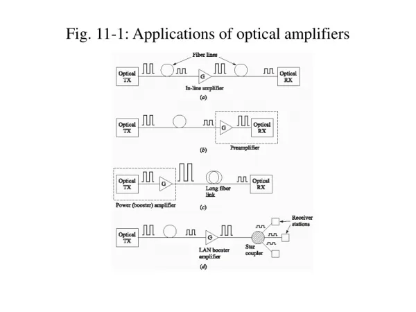
Semiconductor Optical Amplifiers in Avionics. C Michie, W Johnstone , I Andonovic , E Murphy , H White, A Kelly. Semiconductor Optical Amplifiers in Avionics. Significant advantages within Avionics context from use of optical communications networks

E N D
Semiconductor Optical Amplifiers in Avionics C Michie, W Johnstone , I Andonovic , E Murphy , H White, A Kelly
Semiconductor Optical Amplifiers in Avionics • Significant advantages within Avionics context from use of optical communications networks • bandwidth, EMI, significant weight savings • Current systems limited to point to point, multimode • This work • Learn from terrestrial communications using COTS • Focus on PONs – cost is critical • Strategies towards WDM – minimal component inventory • Key operational consideration • Extended temperature range
Long Haul; DWDM systems maximise fibre bandwidth usage TXλ1 TXλ2 TXλX TXλX TXλX TXλX TXλN 40 wavelengths, 200 GHz spacing 10,40, 100+ Gbit/channel
Long Haul; DWDM systems maximise fibre bandwidth usage • Wavelength specific transmitters • single wavelength, DFB • Temperature regulated • Many wavelengths • inventory issues for Avionic system • Temperature Control • increased power consumption • Expensive for Avionics • not a flier!
Passive Optical Networks • High bandwidth Access solutions • Cost is critical – minimise number of components • Minimise manufacturing specification • Operate without cooling if possible • Reflective Semiconductor Based Optical Amplifiers • RSOA – transmitter and amplifier using same component
P λ RSOAs as transmitters P λ CS- RSOA BLS User end
RSOAs as transmitters P λ CS-RSOA CS-RSOA P CS-RSOA BLS Broad Band Source CS-RSOA User
Avionics Link • Simple link • 500 m, 1 Gbit/s • Single Broad band seed source • might need two ? • Multiplexer, de-multiplexer • Minimal cooling/heating
BLS 0.6 dB 0.8 dB 3.5 dB 0.6 dB Rx Rx Rx Tx RSOA Rx Tx RSOA Fibre Link Tx RSOA Tx RSOA Tx RSOA Tx RSOA Tx RSOA Rx Tx RSOA Rx Rx Rx Fibre Link
RSOA Design • InP:InGaAsP • Buried Heterostructure • Lateral Waveguide Tapers • Tensile Bulk • High back refectivity 0.88 • Front facet AR coated RSOA in TO
TO-packaged S-band RSOA parametric tests Standard tests at 25ºC and 80mA
Dynamic Range • Psat ~ 5 dBm, Gain > 20 dB • so we need -15 dBm input to saturate • Can get 0dBm/nm from COTS sources • -5 dBm/nm is obtainable with lower power module • NB the above module needs to be cooled but it should be the only component within the system • To get 12 dB dynamic range (allows 3dB plus of margin) we can allow gain/Psat drop with temperature
RSOA modulation experiments TO packaged devices on ETS evaluation board 50mA DC bias, 60mA modulation S band RSOA, CW injection at 1465 – 1530nm Stage temperature 25°C Modulation at 1.25 Gbps data rate with 211-1 PRBS bit pattern The Rx - APD photoreceiver with limiting amplifier
Sensitivity, Output Power, Gain and Path Loss Capability at 1490nm and 25ºC ~30dB return path loss capability at -20dBm input
Sensitivity, Output Power, Gain and Path Loss Capability at 1580nm and 25ºC
Sensitivity, Output Power, Gain and PLC versus Wavelength at 25ºC -20dBm CW input power and 25ºC stage temperature Eye diagram at 1490nm
S-band device C-band device S, C and L band performance
High Temperature RSOA Design • AlInGaAs • Ridge Waveguide • Single Polarisation • High back refectivity 0.88 • Front facet AR coated 0.01% RSOA in TO
Temperature Performance of RSOA Variable Attenuator Tuneable Laser RSOA Temperature Controlled Mount Optical Spectrum Analyser Evaluate Gain, NF, Psat as a function of temperature. Enables prediction of performance (Power budget for BER 10-9)
Conclusions • WDM PONs enabled by RSOAs • TO packaged polarisation insensitive S band RSOA • ~1dB penalty at 1.25Gbit/s compared to commercial M-Z modulator • High Temperature Operation • AlInGaAs active region • Ridge waveguide design due to oxidation • Single polarisation • Potential to increase operating temperature to > 70 C • Much reduced cooling requirement