Download
1 / 37
390 likes | 537 Views
Aero Space and Ocean Engineering. HokieSat: Virginia Tech’s Nanosatellite Program. Chris Hall Associate Professor Aero Space and Ocean Engineering Virginia Polytechnic Institute and State University. Virginia Polytechnic Institute and State University.

E N D
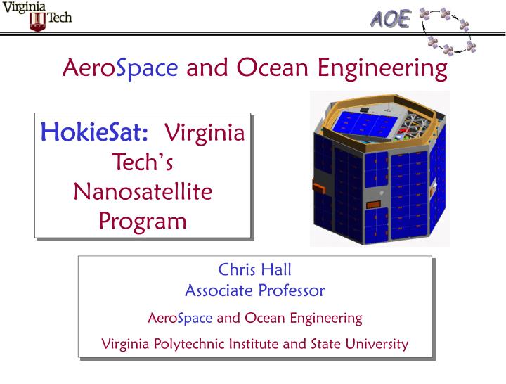
AeroSpace and Ocean Engineering HokieSat:Virginia Tech’s Nanosatellite Program Chris HallAssociate Professor AeroSpace and Ocean Engineering Virginia Polytechnic Institute and State University
Virginia Polytechnic Institute and State University • Founded as a Land Grant College in 1872 • Offers 200 degree programs to 25,000 students • 100 buildings on a 2600 acre campus in Blacksburg • 1500 full-time faculty • $500M annual budget • 8 different colleges Burruss Hall is the main administration building
College of Engineering • Twelve departments offer 15 degree programs at B.S., M.S., and Ph.D. level • Graduate program ranked 16th in the nation by professional engineers and recruiters • ~30 different Research Centers, e.g.: • Commercial Space Communications • Intelligent Materials, Systems, and Structures • Multidisciplinary Analysis and Design Center for Advanced Vehicles (MAD) • More than 300 full-time faculty • Annual research expenditure of more than $60M • 570 M.S. & 99 Ph.D. degrees awarded in 1998 Norris Hall is the main Engineering building
AeroSpace Engineering at Virginia Tech • Aerospace and Ocean Engineering Department Overview • Space Systems Research • Space Systems Design • HokieSat! Randolph Hall houses AOE, as well as Engineering Fundamentals, Mechanical Engineering, and Chemical Engineering
Aerospace and Ocean Engineering • 19 Faculty in • aerodynamics and hydrodynamics • structural mechanics • dynamics and control • design • Yearly graduation rate of approximately • 49-60 Bachelor of Science • 20-25 Master of Science • 8-12 Doctor of Philosophy • $3.5 million annual research funding • Extensive research facilities • Innovative wind tunnels • Water tunnels • Full-scale flight simulator • Spacecraft simulator
National Ranking* 1. Massachusetts Institute of Technology 2. California Institute of Technology 3. Stanford University (CA) 4. University of Michigan–Ann Arbor 5. Georgia Institute of Technology 6. Purdue University–West Lafayette (IN) 7. University of Illinois–Urbana-Champaign 7. University of Texas–Austin 9. Princeton University (NJ) 10. Virginia Tech *Aerospace Engineering Departments in U.S. News and World Report
Recent Faculty Honors • Gene Cliff • 1999 Dean’s Award for Research Excellence • Bernie Grossman • 2000-2001 President Aerospace Department Chairs Association • Chris Hall • 2001 Dean’s Award for Teaching Excellence • Rakesh Kapania • 2000 Dean’s Award for Research Excellence • Fred Lutze • 1999 AIAA Faculty Advisor Award (National Award) • Jim Marchman • 1999 Dean’s Award for Advising • Joe Schetz • 1999 AIAA Contribution to Society Award (National Award) • Roger Simpson • AIAA Vice President - Publications
Space Systems Research • Formation Flying • attitude and orbit dynamics and control • Spacecraft Dynamics and Control • with gimbaled momentum wheels (GMWs) • Integrated Energy Storage and Attitude Control • using high-speed flywheels as “batteries” and GMWs • Optimal Continuous Thrust Orbit Transfer • approximations for indirect methods • Supported by Air Force, NASA, and NSF • Graduated 31 M.S. students and 4 Ph.D. students • Currently advising 7 M.S. students and 1 Ph.D. student • 25 refereed journal articles and 36 conference papers
Senior Design at VT • All seniors complete one year of “capstone” design • two semesters with 3 credit hours each semester • Choose between Aircraft and Spacecraft(Ocean Engineering students choose Ship Design) • Students work in groups of 6 to 12 students • typically include freshmen in second semester • Access to “Senior Design Lab” • PCs, Workstations, Printers, Plotters, Software • Typically compete in national and international design competitions • In 1998, two 1st Place, one 2nd Place, one 3rd Place
Senior Design ‘99 • Aug 1998 - May 1999 • 5 different projects, 7 different teams • Aircraft Projects • 2 projects, 4 teams • 17 AE seniors, 3 AE freshmen, 6 other seniors • international collaboration - 13 British students • industry sponsorship - Boeing & British Aerospace • Spacecraft Projects • 3 projects, 3 teams • 26 AE seniors, 2 AE freshmen, 2 AE juniors • inter-university collaboration - 2 Georgia Tech students • NASA sponsorship - Goddard Space Flight Center
Space Design Projects ‘99 • Single-Stage-to-Orbit Reusable Launch Vehicle Using Rocket-Based Combined Cycle Technology • 8 AE seniors + 2 Georgia Tech students • took 1st Prize in AIAA Design Competition • Virginia Tech Ionospheric Scintillation Measurement Mission • 9 AE seniors, 2 AE freshmen, 2 AE juniors, 20+ EE juniors/seniors • also called “HokieSat” - 1st VT-built spacecraft • 15 kg “nanosatellite” will launch on shuttle in 2003 • funded by Air Force and NASA • Leonardo — a small group of Earth-sensing satellites flying in formation • 8 AE seniors, 1 AE freshman • supporting research sponsored by NASA Goddard
HokieSat University Nanosatellites • Virginia Tech Ionospheric Scintillation Measurement Mission (VTISMM) aka HokieSat • Ionospheric Observation Nanosatellite Formation (ION-F) • Utah State University • University of Washington • Virginia Tech • University Nanosatellite Program • 2 stacks of 3 satellites • Sponsors: AFRL, AFOSR, DARPA, NASA GSFC, SDL AFRL Multi-Satellite Deployment System (MSDS) NASA Shuttle Hitchhiker Experiment Launch System (SHELS)
The ION-F Mission • The Ionospheric Observation Nanosatellite Formation mission addresses the following science topics: • Evolution of ionospheric plasma structure, irregularities and scintillations • Spectral characteristics of ionospheric plasma waves • Global latitudinal distribution of ionospheric plasma structures and irregularities • Accomplished using • Plasma Impedance Probe (PIP) • Global Positioning System (GPS) • Uniqueness of measurements lies in the ability to vary satellite separation • Complement data collected with ground-based radar and concurrent observations from other satellites
ION-F Mission 3CS ION-F USUSat Dawgstar HokieSat Configuration: Multiple Satellite Deployment System Scenario:
Structural Design 2 1 • Design • Analysis • Fabrication • Testing 3 4
Structural Design • 18.25” major diameter hexagonal prism • 12” tall • 39 lbs (~18 kg) • Isogrid Structure • Aluminum 6061 T-651 • Composite Side Panels • 0.23” isogrid • 0.02” skins
External Configuration Solar Cells Crosslink Antenna GPS Antenna LightBand Pulsed Plasma Thrusters Data Port Camera Uplink Antenna Downlink Antenna Science Patches
Internal Configuration Crosslink Components Cameras Power Processing Unit Torque Coils (3) Magnetometer Camera Pulsed Plasma Thrusters (2) Camera Battery Enclosure Downlink Transmitter Electronics Enclosure Rate Gyros (3)
Static Analysis • Requirement: Withstand ±11.0 g accelerations (all directions) • Margin of Safety 0, where • Factor of Safety (FS) • Finite Element Analysis Results
Dynamic Analysis Finite Element Analysis of Isogrid Side Panel (Without Skin) Mode 1 fn = 131 Hz Mode 2 fn = 171 Hz
Dynamic Analysis Finite Element Analysis of Complete Isogrid Structure (Without Skin) Mode 1 fn = 249 Hz
Dynamic Analysis Finite Element Analysis of Complete Isogrid Structure (Without Skin) Mode 2 fn = 263 Hz
Dynamic Analysis Finite Element Analysis of Complete ION-F Stack • Requirement: First mode natural frequency: >100 Hz • Results: First mode natural frequency: 74.6 Hz • Solution: Stiffen joints around attachment points to raise first mode natural frequency ~100Hz
Fabrication Composite structure comprised of 0.23” isogrid and 0.02” skin
Test Requirements • Static test • Stiffness test to simulate expected loading conditions during launch • Sine sweep test • Vibration test to determine free and fixed-base natural frequency • Sine burst test • Vibration test to verify structural strength at extreme loads • Random vibration test • Vibration test to verify structural integrity • Random Vibe Requirements:
Static Testing Strength & stiffness test of structure without skin panels Strength & stiffness test of loading fixture
Static Testing Strength & stiffness test of structure with skin panels • Experiment demonstrated a 32% gain in • stiffness in the cantilever mode due to addition of skins • Skins added less than 8% to the total mass
Dynamic Testing Modal (tap) Testing of Side Panels • Hammer provides impulsive input • Accelerometer measures accelerations used to characterize natural frequencies • Tap testing with and without skins • Verification of predictions of finite element analysis
Dynamic Testing Modal Testing of Side Panels (Without Skin) Mode 1 fn = 131 Hz (vs 131 Hz predicted) Mode 2 fn = 169 Hz (vs 171 Hz predicted)
Dynamic Testing Modal Testing of Side Panels (With Skin) Mode 1 fn = 213 Hz (vs 131 Hz without skin) Mode 2 fn = 453 Hz (vs 169 Hz without skin)
Dynamic Testing Modal Testing of Structure (Without Skins) Mode 2 fn = 272 Hz (vs 263 Hzpredicted) Mode 1 fn = 245 Hz (vs 249 Hz predicted)
Dynamic Testing Z Y X Accelerometer Placement • X-axis control • Y-axis control • Z-axis control • Side panel 1 • Side panel 2 • Zenith panel • GPS (3 axis) • CPU (3 axis) • PPU (3 axis) • Battery box (3 axis) • Structure survived • all tests • Determined component locations to raise natural frequencies
Summary • Aluminum isogrid increases structural performance at reduced mass • Modal testing verifies accuracy of isogrid side panel finite element model within ~1% error • Modal testing demonstrates 26% increase in structural stiffness of side panel by adding thin aluminum skins • Analyses and experiments verify structure satisfies all Shuttle payload requirements
Acknowledgements • Air Force Research Lab • Air Force Office of Scientific Research • Defense Advanced Research Projects Agency • NASA Goddard Space Flight Center • NASA Wallops Flight Facility Test Center • University of Washington • Utah State University • Virginia Tech • Members of ION-F