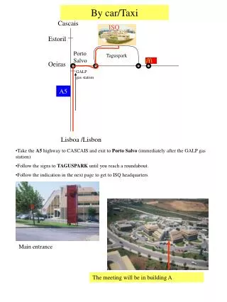
Download
1 / 33
330 likes | 446 Views
Minimizing the Resonant Frequency of MGAS Springs for Seismic Attenuation System in Low Frequency Gravitational Waves Interferometers. Maddalena Mantovani , Juri Agresti, Erika D’Ambrosio, Riccardo De Salvo, Barbara Simoni. Motivations.

E N D
Minimizing the Resonant Frequency of MGAS Springs for Seismic Attenuation System in Low Frequency Gravitational Waves Interferometers Maddalena Mantovani, Juri Agresti, Erika D’Ambrosio, Riccardo De Salvo, Barbara Simoni
Motivations Ground Based Interferometer are Limited by Newtonian Noise under 10 Hz Seismic Attenuation was Designed to Match that Limit Recent Calculations Show the Possibility of Suppression of Newtonian Noise by Suspending the Test Masses in Deep Caves
Cella Suppression of Newtonian Noise *1/100 Underground Seismic Amplitude Suppression of NN by a Factor of 10-6 in Amplitude, 30 in Frequency Seismic Attenuation Must be Redesigned to Match the New Limit Giancarlo Cella Draft Horizontal Achievable with Longer Wires in Wells Vertical Attenuation Requires New Development
Horizontal Attenuation Filter Inverted Pendula
Existing MGAS Spring Magnet Coil Frequency Tuning Control LVDT Practical Limit 200mHz Method to Lower the Resonant Frequency below the Mechanical Limitations LIGO-T010006-00-R
Simulated Noise Apparatus Schematics Mechanical Actuator Actuator Blade Control LVDT Signal 1 Filter to ground LVDT Control Circuit LVDT Driver Signal 2 Ground to Payload LVDT Signal 3 Source Load Spectrum Analyzer
Mechanical Shaking Actuator Mechanical Setup Filter Actuator Blades Control LVDT Filter to ground LVDT Ground to Payload LVDT Signal 1 Control Circuit LVDT Driver Signal 2 Signal 3 Source Load Spectrum Analyzer
Actuator MGAS Blade Control Circuit Variable Gain Control LVDT Thermal Compensation 100÷300 sec • LVDT • Variable Gain • Amplificator-Voice Coil Tunable spring in parallel with MGAS spring ( ) Set Point Integrator Thermal Drift Correction MGAS already neutralize > 90% of cantilever spring stiffness Circuit corrects the last few per cent of stiffness and stabilizes performance
Characterization Work • Determination of the Working Point • Circuit Calibration • Frequency behavior as a function of the Gain • Q Factor Analysis • Impulse Response • Frequency Response
After fixing the vertical height to the minimum frequency point we change the Gain to find the frequency behavior vs. gain
Q Factor Analysis; Two Methods Fitting the Resonant Width in the Transfer Function Fitting the Damped Exponential in Free Oscillations
Transfer Function Measurement (filter body to payload)
Transfer Function with Different Gain values Lowering the system stiffness As the Transfer Function is shifted to lower frequencies, The Q factor decreases
1 3 2 1 2 3
Q Factor Analysis Frequency Response Impulse Response Both methods show a quadratic behavior for the Q factor Implies structural, non viscous, damping
Where is the thermal expansion coefficient given by the Young’s modulus Y y Virginio Sannibale et al. Need for Thermal Compensation Thermal Compensation Circuit 100÷300sec The large thermal dependence of the blade working point with temperature, at low stiffness, makes it practically impossible to obtain very low resonant frequencies
Overnight Blade Tip Position stability Integrated on 10 Period These residuals are mainly the r.m.s. 100 mHz oscillator resonance excited by the seismic activity
Power Considerations The Power consumption is of the order of 10mW
Two Anomalies at Low Frequency are Discovered • Slower Slope in the Lower Frequency Transfer Function Measurements Right 1/f2 Behavior 1/f 1/f 2 1/f 2
Transfer Function Measurements with different Excitation Amplitude The slope does not change
Transfer Function Slope for Different Integration Times The Slope does not depends on the integration time
Slope for Different Vertical Positions Need for more investigations
Second anomaly founded • So far the working point to frequency dependence has always been observed to be hyperbolic, getting narrower at lower frequency • At lower frequency we find a departure from the hyperbolic behavior (the fit in the bottom data set is a fourth power polynomial) • We suppose that higher order effect may be taking over when the anti-spring gets close to fully neutralize the spring constant • The newly observed behavior is coincidental with the departure from 1/f2 of the attenuation transfer function • We do not know yet if the two anomalous effects are correlated.
Is this useful for LIGO?? Vertical Attenuation Horizontal Attenuation the LIGO Deep Fall Back solution prototype for one-pier preattenuators
Bellow equivalent springs Cantilevers 350 Kg Payload DFBS prototype
DFBS Prototype So far driven down to 120mHz despite the additional springs (4/3 of the equivalent bellow stiffness) in fully passive configuration Expect ≤ 30mHz if tuned with electromagnetic anti-spring attenuation plateau at 10-3 proven on preceding prototypes (expect similar performance)
Conclusions • This development of Electromagnetic Correction Springs was designed to boost the Low Frequency attenuation performance of Geometric Anti Springs for future Underground Low Frequency Gravitational Wave Interferometric Detectors (Horizontal Attenuation was always easily available) • This development allows for further depression of seismic perturbations, beyond the performance of the Superattenuators, reaching down to 1 Hz and even below.
Conclusions • The retrofitting of this technology on existing system like the LIGO deep fall back pre-isolator solution may allow the introduction of attenuation factors as large as one thousand for frequencies above 1 Hertz • Sizeable attenuation at the micro seismic peak at 150 mHz can be obtained as well
Next Steps • Find the source of the less then 1/f2 behavior • Repeat the Measurements with Accelerometers • Study and Reduce the Control Circuit Noise Improving some of its Performances (Yanyi Chen) • Make a Mechanical Thermal Compensation • Use this Seismic Attenuation System on the Mexican Hat Interferometer (Barbara Simoni)