Download
1 / 63
630 likes | 714 Views
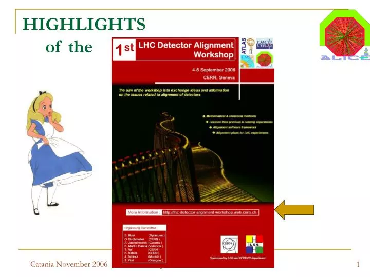
HIGHLIGHTS of the. Why this Workshop ?. New level of complexity and precision of the LHC detectors Hitting limits of the actual alignment methods (matrix inversion) Discovery potential of LHC could be compromised by alignment problems

E N D
HIGHLIGHTS of the Adam Jacholkowski/ALICE
Why this Workshop ? • New level of complexity and precision of the LHC detectors • Hitting limits of the actual alignment methods (matrix inversion) • Discovery potential of LHC could be compromised by alignment problems • Need of sharing methods and experience between different LHC experiments • Learning from past experiments in order to be ready at Day 1 Adam Jacholkowski/ALICE
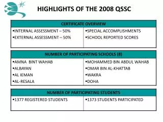
PARTICIPANTS (Σ≈ 100 !) • ATLAS – 29 • CMS – 30 • LHCb – 18 • ALICE – 5 +1 • TOTEM - 4 • Others - ~ 10 Adam Jacholkowski/ALICE
PROGRAM MONDAY • Introduction – alignment challenges: ATLAS, CMS, LHCb, ALICE (by AJ) • Mathematical methods & algorithms • Alignment algorithms (Volker Blobel) • Alignment using a Kalman Filter Techniques (Rudi Fruehwirth) • Alignment experience from other experiments: STAR, BABAR, ZEUS/H1, SLD, CDF TUESDAY • Overviews of selected topics (covering all LHC experiments) • Detector description (geometrical modelers) (by Cvetan) • Tracking software & algorithms • Impact of misalignment on physics • Validation of the alignment Adam Jacholkowski/ALICE
PROGRAM – cont. • Alignment strategy for the LHC experiments • LHC machine plans (Mike Lamont, AB-OP) • Strategy from CMS • Strategy from ATLAS • Strategy from LHCb • Strategy from ALICE (Javier, Raffaele, Marian) • Workshop dinner WENDSDAY • Alignment survey data (Christian Lasseur et al. ,TS-SU ) • Workshop Summary (Dave Brown) • Round Table discussion: workshop continuation ?, focus of the next meeting, documentation (Yellow Report ?), organization of the inter-collaborative work, lessons learnt … Adam Jacholkowski/ALICE
LHC DETECTOR ALIGNMENT CHALLENGES • Detector presentation: mechanics, granularity (# of degrees of freedom), hardware align. systems • Sources of misalignments: mechanical precision and stability, sensitivity to B, thermal effects, aging etc • Methods and software tools for realignment and alignment validation • Impacts of misalignment on physics performance, • Goals (≤ 20% degradation due to misalignment for ex.) expected problems (practical and numerical) Adam Jacholkowski/ALICE
Tracking requirements ATLAS ID TDR impact parameter Degradation due to geometry knowledge: <20% on impact parameter and momentum Florian Bauer, 4/9/2006, LHC Alignment Workshop • Reasonable goal: • Pixel: sRF= 7 mm • SCT: sRF= 12 mm • TRT: sRF= 30 mm Furthermore studies of impact of SCT+Pixel random misalignment on B-Tagging abilities show: light jet reduction get worse by 10% for sRF=10mm light jet reduction get worse by 30% for sRF=20mm momentum S. Corréard et al, ATL-COM-PHYS-2003-049 Adam Jacholkowski/ALICE 11
Software requirements • ID consists of 1744 Pixel, 4088 SCT and 124 TRT modules • => 5956 modules x 6 DoF ~ 35.000 DoFs • This implies an inversion of a 35k x 35k matrix (Millepede) • Use calibration as X-ray and 3Dim measurements to setup • best initial geometry • combine information of tracks and optical measurements like FSI. • Reduce weakly determined modes using constraints: • vertex position, track parameters from other tracking detectors, • Mass constraints of known resonances, overlap hits, modelling, • E/p constraint from calorimeters, known mechanical properties etc. • ability to provide alignment constants 24h after data taking • (Atlas events should be reconstructed within that time) (frequency scanning interferometry) Adam Jacholkowski/ALICE 13 Florian Bauer, 4/9/2006, LHC Alignment Workshop
Many approaches • Global c2 minimisation (the 35k x 35k inversion) • Local c2minimisation (correlations between modules put to 0, invert only the sub-matrices, iterative method) • Robust Alignment (Use overlap residuals for determining relative module to module misalignment, iterative method) Furthermore work done on: • Runtime alignment system (FSI) • B-field Adam Jacholkowski/ALICE 14 Florian Bauer, 4/9/2006, LHC Alignment Workshop
Alignment Software requirements • Describe detector taking into account calibration for all optical elements, chambers. • Description is 80% of the alignment software job…. Visualisation tools vital. • Ability to combine optical information with straight or High Pt tracks • Describe the 9 chamber deformations parameters: in the fit 6 + 9 DoFs per chamber. • Handle up to 10.000 DoFs in the Barrel and roughly the same in the Endcap • Run online (1 correction per hour) with a latency of 24h. • robust algorithms, automated dataflow, monitoring, use of Databases as IO Today we have 2 alignment softwares: ASAP describing the Barrel alignment AraMyS describing the EndCap alignment ASAP: uses iterative c2 fit, segmentation into sub-alignments foreseen AraMys: Minuit, segmentation into sub-alignments Adam Jacholkowski/ALICE 23 Florian Bauer, 4/9/2006, LHC Alignment Workshop
Conclusion ( ……………………………………………………………) • Installation and validation of the Muon hardware alignment components on the way • Muon: optical alignment software exists and validated at H8 test-beam • Muon straight and High Pt track alignment still under development • Inner tracker alignment: many algorithms exists today • Validation in the H8 test beam done • Between ATLAS Inner Tracker and Muon Spectrometer • many synergies can be gained ! • This should be even more true on LHC level! Adam Jacholkowski/ALICE 26 Florian Bauer, 4/9/2006, LHC Alignment Workshop
Tracking System Challenges (LHCb , by Steve Blusk) • Large track density • Trigger uses tracking info • Requires good alignment • Online updating of constants if needed. • Tracking algorithms need to be FAST, as they are executed online.Want offline pattern recognition very similar to online version, except for fine tuning of alignment & calibrations. • Minimize material (no surprise here) Adam Jacholkowski/ALICE
Vertex Detector Challenges • Most precise device in LHCb moves • Retracted by ~ 3 cm in-between fills • Reinserted to ~ 8 mm after stable beams • Integral part of the trigger • RZ (2D) tracking/trigger scheme requirestransverse alignment between modules < 20mm. • Internal alignment monitoring/updatingas necessary (online vs offline), 2D vs 3D • Rest of tracking system (online vs offline) • Momentum estimate using VELO-TTin HLT. • Need for “same” tracking in HLTand offline: tradeoffs of speed/efficiency/ghost rate ~4% ghost rate (3D) ~7% ghost rate (2D) M. Needham Adam Jacholkowski/ALICE
Software Alignment at LHCb Generated MC Particles • General Strategies • Magnet OFF data crucial • Separate magnetic field effects from geometrical ones. • Commissioning • After access to service tracking system • Otherwise, periodically, based onunexplainable change in alignment • Pre-selected track samples • Low multiplicity events • Isolation requirements around track (if necessary) • Magnet OFF: Use energy from calorimeter • Magnet ON data • Tweak alignments from Magnet OFF • Cross-check with Ks, J/y, U, DKp, Z0, etc (after dE/dx corrections and B field map validated) XZ View Reconstructed Event Adam Jacholkowski/ALICE
Y axis Random Velo Misalignment Mechanical placement, s <20 mm, S. Viret Impact Parameter Resolution (in mm) (Velo = Vertex Locator) Adam Jacholkowski/ALICE
(LHCb challenge) Summary • LHCb Trigger requires “good” online alignment. • Extraction/re-insertion of VELO every fill requires updating of some subset of alignment constants • Probably default alignment constants from previous run to start off(aside from an overall DX (DY) from VELO motion controller between fills) • Always update ? Or only when significant change? • Large number of planes and overlap regions facilitate alignment between detectors • Magnet OFF data critical to decoupling geometry from B field effects • More work needed on proving that dE/dx and B field mapping “issues”can be de-convoluted. • Fine tuning of alignment for final offline analysis. • Software Alignment Monitoring: • Low-level: #Hits/track, c2, IP, residuals, #tracks/event, etc • High level: Masses, mass resolutions, relative particle yields. Adam Jacholkowski/ALICE
ALICE Alignment Challenge (A Large/LHC Ion Collider Experiment) • OUTLINE • physics @ ALICE • ALICE detectors • software framework • tracking & vertexing • alignment aspects • and challenges ITS (Inner Tracking System) Adam Jacholkowski/ALICE
ITS – Inner Tracker System Material Budget: ≤ 1% X0 per layer ! SSD SDD SPD Lout=97.6 cm Rout=43.6 cm • 6 layers, three technologies (keep occupancy at a few % for max multiplicity) • SPD: silicon pixels (0.2 m2, two layers, 9.8 M channels, 240 modules) • SDD: silicon drift (1.3 m2, two layers, 133 k channels, 260 modules) • SSD: double-sided silicon strips (4.9 m2, two layers, 2.6 M channels, 1698 modules) Adam Jacholkowski/ALICE
ALICE acceptance D0 decay c/b hadron Central Barrel c/b hadron + - channel (Muon arm) Adam Jacholkowski/ALICE
Detector/Reconstruction performance Tracks and Vertices
At beam axis sx = 15 mm sy = 15 mm sz = 5 mm 1cm off beam axis sx = 25 mm sy = 25 mm sz = 5 mm Correlation of two innermost pixel layers (tracklets !) main vertex resolution Main Vertex Resolution 2 pixel sectors (out of 10 total) beam pipe Adam Jacholkowski/ALICE
resolution ~ 5% at 100 GeV/c excellent performance in hard region! dN/dy = 4000, B=0.4 T Tracking Performance p (GeV/c) For track densities dN/dy = 2000 – 8000,combined tracking efficiency above 90% with <5% fake track probability Adam Jacholkowski/ALICE
PHYSICS PERFORMANCE few examples:
1. Particle correlations, resonances Two pion momentum correlation (HBT) analysis Studies on event mixing and two track resolutions. Investigated track splitting/merging and pair purity. Calculated momentum resolution corrections and PID corrections Radii can be recontructed up to 15 fm r0(770)p+p- 106central Pb-Pb Mass resolution ~ 2-3 MeV In medium modifications of mass, width, hadronic and leptonic channels; partial chiral symmetry restoration Adam Jacholkowski/ALICE
2. Impact Parameter resolution Impact parameter resolution is crucial for the detection of short-lived particles: charm and beauty mesons and baryons. Determined by pixel detectors: at least one component has to be better than 100 mm (ct for D0 meson is 123 mm) impact parameter d0 (rf) better than 40 µm for pT> 2.3 GeV/c ~20 µm at high pT Position Mass Momentum Efficiency resolution resolution resolution K0s 200300 mm 68 MeV 1.51.8% 2125% L500 mm 34 MeV 1.3% 15% Adam Jacholkowski/ALICE
Mass 1.864 GeV/c2 c=124 m 3.Open Charm Detection in Hadronic Decays ~0.55 D0K-+ accepted/event important also for J/ normalization Adam Jacholkowski/ALICE
rec. track e Primary Vertex B X d0 4.Beauty via displaced electrons • ALICE has excellent electron identification capabilities (TRD) • Displaced electrons from B decays can be tagged by an impact parameter cut Adam Jacholkowski/ALICE
acceptance: pt > 0.2 GeV/c rf < 50 mm for pt > 1.5 GeV/c acceptance: pt > 1 GeV/c rf < 50 mm for pt > 2.5 GeV/c B = 0.5 T B = 4 T Dpt/pt < 2% up to 100 GeV/c Dpt/pt < 2.5% up to 20 GeV/c < 3% up to 100 GeV/c 5. Open Charm: ALICE vs CMS (A. Dainese @ Hard Probes) • D mesons ct ~ 100–300 mm, B mesons ct ~ 500 mm • Secondary vertex capabilities! Impact param. resolution! Adam Jacholkowski/ALICE
5. Bottonia: Alice vs CMS & Atlas Bkg input: dNch/dy~2500-4000 in central Pb-Pb. for 1 month central central min. bias central |h|<0.8 |h|<2.4 Adam Jacholkowski/ALICE
Impact of misalignment on Physics • All physics performance figures obtained with the perfect geometry (same for the ALICE Phys. Progress Report) • γ mass resolution as a function of misalignment (in Muon Arm) studied (see talk by J Castillo) • This summer Physics Data Challenge (PDC06) • (hypothetical) residual misalignment in • part of the simulation with the full misalignment(expected Day-1 misalignment) • Analysis of the PDC06 data assessment of the physics quality degradation due to misalignment (underway !) Adam Jacholkowski/ALICE
Alignment Challenges • Initial misalignment within specifications (50 – 200 μm) • Inner Tracking System robust track based alignment 10 micron alignment precision goal • TPC calibration & alignment (ExB effect !) • Muon Arm & TPC ITS alignment • TRD,TOF, RICH(HMPID)... inter - detector alignment • Fast alignment and validation procedures (during data taking!) Condition Data Base • Alignment stability monitoring (hardware & software) Alignable elements: SPD -- 240 SDD -- 260 SSD - 1698 Total – 2198 Adam Jacholkowski/ALICE
Mathematical Methods andAlgorithms • Alignment algorithms (V. Blobel), overview of the most frequently used algorithms, more detailed presentation of the Millepede algorithm and its developments (Millepede II) http://www.desy.de/~blobel • Alignment using a Kalman Filter technique (R. Fruehwirth) – a novel approach in which Kalman Filter is used alternatively for tracking and alignment parameters update Adam Jacholkowski/ALICE
(Kalman Filter) Adam Jacholkowski/ALICE
Alignment experience from otherexperiments • STAR (S. Margetis) Alignment/Calibrations affect everything DCA-XY ~ 140mm / p(GeV) Remember this number Drifting complicates the Alignment process If you have drift detectors make sure you have plenty of redundant monitoring systems (lasers, charge injectors etc. Adam Jacholkowski/ALICE
TPC TPC +SSD +SSD +SVT1,2,3 +SVT1,2,3 1/p 1/p DATA (STAR) • Resolution here includes vertex and hit resolutions. Real values 20% smaller • At infinite momentum limit is ~150um in XY and 80um in Z (~vertex resolution in CuCu) • At 1 GeV/c it is 220um in XY and 150 in Z • Z is our good (not drifting) coordinate! • We are on a good path Adam Jacholkowski/ALICE
Summary (S. Margetis for STAR) • Recent interest in charm physics re-focused STAR’s interest in its vertex detectors • The presence of drift silicon technology (like in ALICE) complicates the task of Alignment • but also presence of non-drifting detectors (strips or pixels) will prove invaluable • Our Global Alignment approach and techniques were successful to overall shifts better than 20 mkm • which for this device is sufficient • The Self-Alignment methods are still under development. • STAR has a funded R&D active pixel effort for an ultra thin device @ 2cm from the vertex Adam Jacholkowski/ALICE
Overview talks for selected topics(all LHC experiments) • Detector Description (Cvetan) – different systems but large (logical) similarities • Tracking software & algorithms (A. Strandlie) – including input from ALICE (from Marian) • Impact of Misalignment on physics (G. Steinbrueck) – a lot of study in other LHC experiments, from ALICE only MUON results on Y family resolution • Validation of the Alignment (T. Golling) – private discussions (Raffaele and me with Tobias), many ideas, some experiment dependent features Adam Jacholkowski/ALICE