Download
1 / 13
130 likes | 297 Views
HF Wideband Active Circulator Team Laplace Sauce: Jake Smith & Andrew Wajda Sponsors: Dr. Jeff Young & Dr. Ken Noren.

E N D
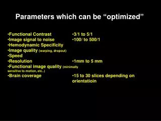
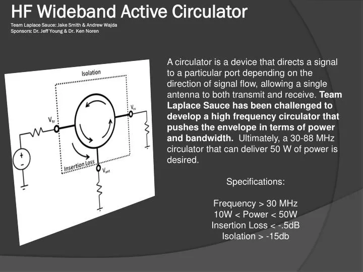
HF Wideband Active CirculatorTeam Laplace Sauce: Jake Smith & Andrew WajdaSponsors: Dr. Jeff Young & Dr. Ken Noren A circulator is a device that directs a signal to a particular port depending on the direction of signal flow, allowing a single antenna to both transmit and receive. Team Laplace Sauce has been challenged to develop a high frequency circulator that pushes the envelope in terms of power and bandwidth. Ultimately, a 30-88 MHz circulator that can deliver 50 W of power is desired. Specifications: Frequency > 30 MHz 10W < Power < 50W Insertion Loss < -.5dB Isolation > -15db
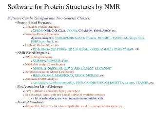
Three Stage Transistor DesignFrom S. Tanaka IEEE article: Active Circulators – “The Realization of Circulators using Transistors” 1965 Tanaka showed that devices with certain two-port system parameters can be turned into circulators.
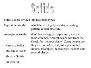
Two NPN circulators were realized.Results and Lessons Learned: 2N3904 NPN General Purpose Amplifier MPSH10 NPN RF Transistor Purpose: To test theory at low frequencies. Results: Very good circulator behavior for 1-10MHz. Conclusion: The 3904 is an excellent benchmark to test new methods on that in the future we may want to employ on other transistors. Purpose: To construct a circulator for the frequencies 30-80 MHz Results: Weak circulation at frequencies 30-50MHz due to large insertion loss. Conclusion: Much more detail and concern must be taken at these frequencies. Stability, noise, ringing, and unwanted coupling are all issues that need to be addressed.
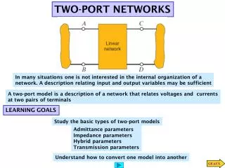
Op-Amp Approach to Active Circulators For the circulator topology shown to the left, the performance relies mainly on the Op-Amp. To meet the required specifications, choosing the correct Op-Amp is essential.
Op-Amp Considerations Slew Rate- This is the rate of change of the op amp's voltage output over time when its gain is set to unity (Gain =1). Maximum peak output voltage swing - The maximum peak-to-peak output voltage that can be obtained without clipping when the op amp is operated from a bipolar supply. Gain-Bandwidth Product- This is the product of the op amp's open-loop voltage gain and the frequency at which it was measured. Current vs. Voltage Feedback?
Final Design Components Used Op-Amp: Texas Instruments THS3061 Cost: $6.79 each (3 used) Trim Pot: Vishay 43P501 500 Ω, 15 turns Cost: $1.43 each (15 used) Connector: AMPHENOL BNC R/A Jack Cost: $2.94 each (3 used) Total Cost: $50.64
Testing & Results Two methods of testing were used to determine the capabilities of the Op-Amp circulator: Method 1: A signal was sent through the circulator using a function generator and then the signal was observed at each output port using an oscilloscope. Isolation was then determined from the gain seen between the two output ports. Frequency was then increased until either signal distortion occurred or the isolation specification was violated. Results: Maximum frequency was unable to determined. The function generator in the senior design lab was maxed out at 15MHz at 1 Vpp. Method 2: Used an Agilent N5250C Network Analyzer to determine the S-Parameters. The network analyzer was programmed to sweep frequencies from 10-100MHz. Results: Maximum frequency was found at 44.38 MHz. The limiting s-parameters were the reflection coefficients, S11 & S22.
Conclusion • While we were able to meet the frequency specification for our circulator, we were unable to achieve the power aspect. • With current available Op-Amp technology, circulating a signal in the MHz range with 50W of power is unachievable. • However, readily available RF transistor technology can bring us well into both frequency and power specifications. The S-Parameters of such devices are often recorded on their data sheets, and as such they can be used to design a circulator using the Tanaka’s equations.